11 “Power+” +0500048IE - rel 2.2 - 06.11.2014
ENG
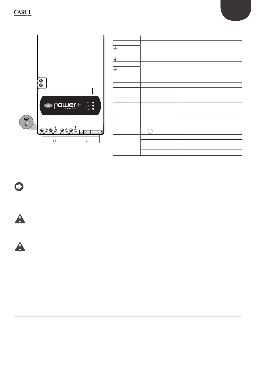
Description of the terminals
F
E
L2/N L3 U V W
C1
C2
L1/L
1 2 345 678910
Fig. 3.g
Rif. Description
L1/L, L2/N, L3 Three-phase power supply input
earth
(*)
L1/L, L2/N Single-phase power supply input
earth
(*)
U, V, W Motor output
earth
(*)
C1, C2 Terminal block not used in PSD10**2**. For optional
external DC Choke in PSD10184** e PSD10244**
1, 2 Relay output
3 0 V RS485/ModBus® connection
4 RX+/TX+
5 RX-/TX-
6 PTC Input
7 24 Vdc Auxiliary voltage
80V
9 STOa Safe Torque Off digital input (**)
10 STOb
E
PE
F (Led) POWER (green) drive powered
RUN/FAULT
(green/red)
drive running / drive alarm
DATA (yellow) communication active
(*) The earth connections inside the drive are electrically connected together and to PE.
(**) To enable the drive for operation, apply a voltage of 24 Vac/Vdc to the Safe Torque Off digital input. The polarity is
indiff erent for direct current power supply.
Note:
the group of terminals for control signals 3...10 and the group of terminals for relay 1,2 have double insulation
between each other and with reference to the power terminals.
Warning: the max tightening torque is:
• power terminals: 1,5 Nm;
• control terminals: 0,5 Nm.
Important:
• in the European Union, all units that incorporate the drive must comply with the Machinery Directive 2006/42/EC.
Specifi cally, the manufacturer of the unit is responsible for the installation of a main switch and the conformity to
standard EN 60204-1;
• for fi xed installations according to IEC61800-5-1, a disconnect device is required on the circuit between the power
supply and the drive;
• only use permanently wired power input connections; the drive must be earthed: the earth wire must be sized for
the maximum fault current that is normally limited by the fuses or a circuit breaker.
3.7 Conformity to EMC standards
As regards the general EMC guidelines, strictly follow the instructions shown in the paragraph on “Electrical
connections“ and in the user manual code +0300048EN, downloadable, even prior to purchase, from www.carel.com.