Do you have a question about the Carel Power+ and is the answer not in the manual?
Essential instructions for safe operation and documentation.
Important safety warnings regarding product use and installation.
Guidelines for proper disposal of waste electrical and electronic equipment.
Description of safety symbols used in the manual.
Warnings concerning installation, operation, and maintenance of the drive.
Critical safety rules to follow before performing any maintenance work.
Overview of the drive's capabilities and key characteristics.
Description of different Power+ drive models available.
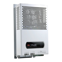
How to identify the drive using its rating plate.
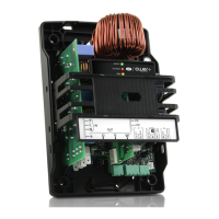
Details on the physical structure and overall dimensions of the drive.
Instructions for drilling mounting holes and assembling the drive.
Guidelines for proper cooling and ventilation of the drive.
Procedures for safe and correct electrical installation.
Information on meeting Electromagnetic Compatibility (EMC) standards.
Step-by-step instructions for all electrical connections.
Considerations for earth leakage current and protection devices.
Instructions for connecting the motor power cable for correct rotation.
Connecting the Safety Torque Off input for safety functions.
Setting up serial communication via RS485 Modbus®.
Illustrating electrical layouts for single-phase and three-phase models.
Comprehensive diagram of all electrical connections for the Power+ drive.
Details on Coldplate models and their installation requirements.
Information on the PFC coil and its connection for single-phase models.
Instructions for installing the optional DC choke for three-phase models.
Guidelines for connecting the EMI filter for single-phase models.
Setting drive parameters for motor control, communication, and startup.
Configuring network address, baudrate, and parity.
Choosing between PM brushless, vector, or V/f control.
Parameters for configuring PM brushless motors.
Parameters for asynchronous motors with vector control.
Parameters for asynchronous motors with V/f control.
Steps for automatic measurement and configuration of motor parameters.
Essential checks to perform before commissioning the drive.
Description of drive inputs and outputs.
Programming the relay output function.
Setting minimum and maximum output frequency.
Inverting the motor's direction of rotation.
Setting up a programmable speed profile.
Defining how the speed profile is executed.
Adjusting the IGBT switching frequency.
Choosing between ramp stop or coast stop.
Enabling or disabling the flying restart function.
Detailed explanation of V/f control for asynchronous motors.
Optimizing start-up current for motors.
Configuring PI parameters for speed control.
Commands for Run/Stop, Reset, and setting frequency.
Reading drive status, alarms, and operating data.
Overview of Modbus® functions supported.
Avoiding specific frequencies to prevent mechanical resonance.
Automatically reducing switching frequency to prevent overtemperature.
Reducing motor speed to prevent drive overtemperature.
Comprehensive list and description of drive parameters.
Parameters related to speed profiles, switching frequency, and relay configuration.
Parameters for Modbus® communication and drive addressing.
Parameters for motor control modes, start-up, and current limits.
Parameters for motor resistance, inductance, and power factor.
Commands for Run/Stop, Reset, Autotuning, and frequency setting.
Detailed description of status variables and registers.
Variables for motor frequency, current, voltage, and system status.
Information on stored alarms and drive identification.
Classification of drive and motor malfunctioning alarms.
How alarms are logged and reset.
Table of alarm codes, causes, and solutions.
Codes for Modbus® communication errors.
Configuration and setup for motor overtemperature alarms.
Handling serial communication fault timeouts.
Using the relay output to signal drive alarms.
Operating conditions, power supply, and output specifications.
Rated currents, cable sizing, and fuse recommendations.
Formulas for converting frequency, RPS, and RPM.
Table for converting frequency to motor speed.
| Protection degree | IP20 |
|---|---|
| Rated Power | 0.75-630kW |
| Communication | Modbus RTU |
| Operating Temperature | -10°C to +50°C |
| Cooling method | Forced ventilation |
| Ambient temperature range | -10°C to +50°C |
| Relative humidity | < 95% non-condensing |
| Storage temperature range | -20...+70 °C (-4...+158 °F) |