ENG
“Power+” +0300050EN - rel. 2.3 - 08.06.2012 10
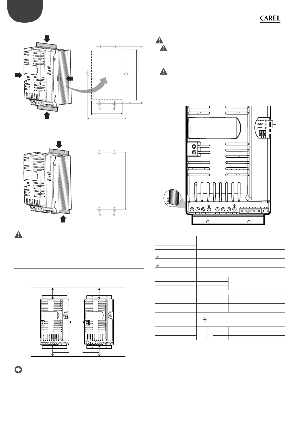
Installation with heat sink outside of the panel
80
145,6
243
289,2
138
192,3
Fig. 3.d
Panel installation
80
269,3
Fig. 3.e
Important: in case of dismantling, do not grab the brackets, but rather
the “solid“ parts such as the heat sink and the plastic cover.
3.5 Cooling
All the Power+ drives, Coldplate models excluded, are tted with cooling
fans. There must be su cient air ow and air change inside the electrical
panel. Refer to table 9.1 for maximum heat dissipation values.
≥ 10 mm
≥ 200 mm
≥ 200 mm
Fig. 3.f
Note:
• on single-phase models leave space to t the PFC coil;
• on three-phase models space may be needed to t a DC choke (see par.
3.8).
3.6 Electrical installation
Important:
• before carrying out any maintenance work, disconnect the drive and
the external control circuits from the power supply by moving the main
system switch to “o ”. Once power has been disconnected from the drive,
wait at least 5 minutes before disconnecting the electrical cables;
• always make sure the motor has stopped completely. Motors that
are still freely rotating may produce dangerous voltages at the Power+
terminals, even when this is disconnected from the power supply.
Description of the terminals
C1
L1/L L2/N L3 U V W
G
F
C2
E
Fig. 3.g
Ref. Description
L1/L, L2/N, L3 Three-phase power supply input
earth connection (*)
L1/L, L2/N Single-phase power supply input
earth connection (*)
U, V, W Motor output
earth connection (*)
C1, C2 Terminals for connecting the PFC coil for single-phase
drives or optional DC choke for three-phase drives
10V
RS485/ModBus® connection
2 RX+/TX+
3 RX-/TX-
4 PTC Input
5 24Vdc Auxiliary voltage
60V
7 STOa Safety Torque O digital input (**)
8STOb
9, 10 Relay output
E
PE
F Microswitches for setting the network address
G Led
{
POWER = drive powered
FAULT = active alarm
DATA = communication active
Tab. 3.c
(*) The earth connections inside the drive are electrically connected together
and to PE.
(**) To enable the drive for operation, apply a voltage of 24 Vac/Vdc to the
Safety Torque O digital input. The polarity is indi erent for direct current
power supply.