ENG
“Power+” +0300050EN - rel. 2.3 - 08.06.201221
5. FUNCTIONS
5.1 Inputs and outputs
Inputs
The inputs include:
1. the single or three-phase power supply, depending on the model, which
must be connected selecting suitable cables and fuses according to the
table in paragraph 9.1;
2. the “Safety Torque O ” safety digital input, to which an alternating or
direct voltage source is connected along with a safety device. See the
main connection layout;
3. the PTC thermistor for motor overtemperature protection. Must be
selected for motor protection and in a way that at the alarm temperature
the resistance is > 2600 ohm.
Important: in order to use the PTC input, the motor overtemperature
alarm must be enabled. See the paragraph 8.5.
Outputs
The drive outputs include:
1. the motor output, to which the cables must be connected, which are
dimensioned according to the table in paragraph 9.1;
2. the relay output.
5.2 Relay con guration
The relay function can be programmed and can indicate a functioning
condition of the drive or an alarm. See the chapter 8 “ALARMS” for the latter
case. The relay contact closes if the corresponding event occurs.
Mod.
add.
Description Def Min Max U.M. R/W
26 Relay con guration
0: drive in alarm
1: fan running
2: drive overtemperature alarm
3: motor overtemperature alarm
4: motor overload alarm
5: overvoltage alarm
6: undervoltage alarm
7: speed derating in progress
8: motor running
008-R/W
Tab. 5.a
5.3 Minimum and maximum output
frequency
The parameters allow to set the minimum and maximum limit for the drive
output frequency. The frequency set point must also be within the limits
xed by minimum and maximum frequency, otherwise it is not accepted.
Mod.
add.
Description Def Min Max U.M. R/W
6 Maximum output frequency 0 0 5000 0.1Hz R/W
7 Minimum output frequency 0 0 5000 0.1Hz R/W
Tab. 5.b
5.4 Direction of rotation inversion
During drive commissioning, in order to change the direction of rotation of
the motor, it is possible to swap over two of U, V, W wires. In the event of
application with compressors, there is only one motor rotation direction. In
other cases it is possible also to enable the reverse direction of rotation with
the relative parameter.
Mod.
add.
Description Def Min Max U.M. R/W
8 Reverse speed enable 0/1 = no/yes 0 0 1 - R/W
Tab. 5.c
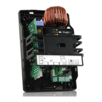
5.5 Speed pro le
Power+ has been designed with a programmable speed pro le for adaptation
to the features requested on compressor start-up. Once the speed pro le has
been selected it is also possible to establish the method of execution. The
pro le is designed by three frequencies (f1, f2, f3), which must be reached
with three linear ramp trends, de ned via three accelerations (a1, a2, a3).
Once the frequency (i=1, 2, 3) has been reached, the frequency value
remains for the time ti (i=1, 2, 3). Regarding decrease in speed, it is possible to
set just one deceleration.
f1
t2
t1
f2
f3
t3
a1
a2
a3
a4
f (Hz)
t
Fig. 5.a
Key
f1/ f2/ f3
Frequency 1/2/3
f
Frequency
a1/a2/a3/a4
Acceleration 1/2/3/4
t
Time
t1/ t2 /t3
Delay 1/2/3
Mod.
add.
Description Def Min Max U.M. R/W
12 Speed pro le: frequency 1 0 0 5000 0.1Hz R/W
13 Speed pro le: frequency 2 0 0 5000 0.1Hz R/W
14 Speed pro le: frequency 3 0 0 5000 0.1Hz R/W
15 Speed pro le: acceleration 1 60 0 500 0.1Hz/s R/W
16 Speed pro le: acceleration 2 60 0 500 0.1Hz/s R/W
17 Speed pro le: acceleration 3 60 0 500 0.1Hz/s R/W
18 Speed pro le: acceleration 4 60 0 500 0.1Hz/s R/W
19 Speed pro le: stand-by time 1 0 0 600 s R/W
20 Speed pro le: delay 2 0 0 600 s R/W
21 Speed pro le: delay 3 0 0 600 s R/W
23 Speed pro le: deceleration 60 0 500 0.1Hz/s R/W
Tab. 5.d
Note: it is recommended to use the values indicated by CAREL in
relation to the compressor used, as they guarantee the functioning mode
speci ed by the manufacturer. Alternatively it is possible to set a simple pro le
(f2=f3=Fmax; t1=t2=t3=0; a2=a3=a4=maximum acceleration allowed) and
refer management of the accelerations and delay times to the external
control. However, in this case it is necessary to keep the values of a1 and f1
indicated by CAREL, as they are critical for the compressor start-up phase.