ENG
“Power+” +0300050EN - rel. 2.3 - 08.06.2012 22
5.6 Speed pro le: execution mode
It is possible to de ne the execution mode of the speed pro le with bit0, i.e.
if the individual delays must be performed just one time or if they must be
carried out every time the frequency set point exceeds one of the f1, f2, f3
frequencies. If the frequency set point is decreased, the deceleration set is
respected.
Mod.
add.
Description Def Min Max U.M. R/W
22 Speed pro le: execution mode (2 bit
parameter)
bit meaning 0/1
0 delay
execution
always/only once at
every start-up
1 force freq. 2 no/at start-up
3 0 3 - R/W
Tab. 5.e
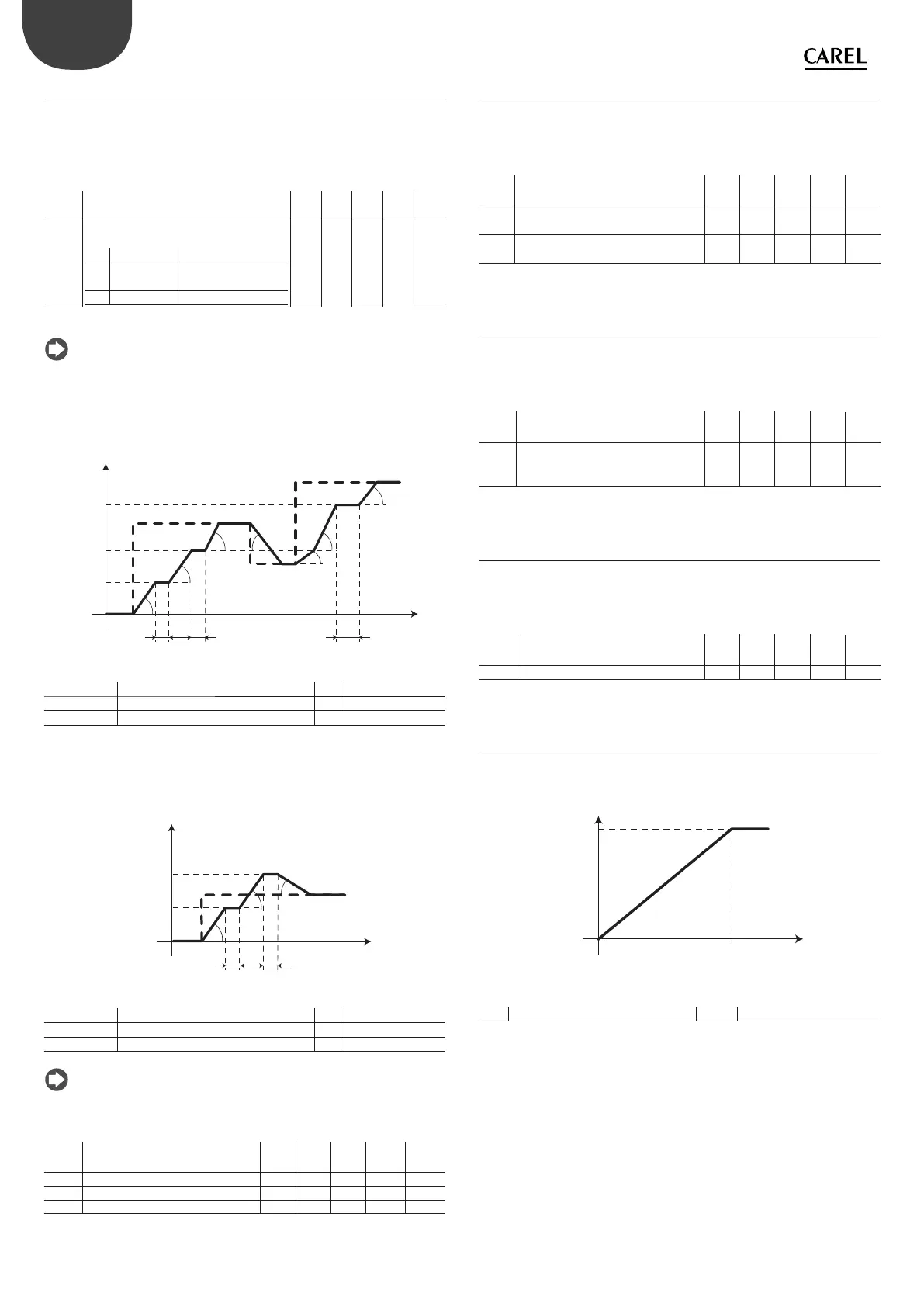
Note: if the bit0=1 and the frequency set point is between frequency
2 and frequency 3, the speed pro le will be performed respecting delays t1
and t2. If the frequency set point successively decreases to a value below
f2, the frequency is reached with the deceleration de ned at the relative
parameter. If the frequency set point nally increases to a frequency value
greater than f3, only delay t3 is respected.
t
f (Hz)
f1
t1
f2
f3
t3
a1
a2
a3
a4
a2
a3
d
setpoint
t2
Fig. 5.b
Key
f1/ f2/ f3
Characteristic frequency 1/2/3
f
Frequency
a1/a2/a3/a4
Deceleration/ Acceleration 1/2/3/4
t
Time
t1/ t2 /t3
Delay 1/2/3
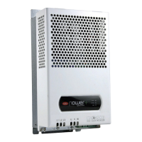
The bit1 is considered only if the frequency set point on start-up is lower than
frequency 2 of the pro le. If bit1=1, frequency 2 is always reached on start-up
respecting delays t1 and t2. The frequency set point is then reached with the
deceleration de ned by the relative parameter.
W
I+]
f1
f2
a1
a2
d
setpoint
t1 t2
Fig. 5.c
Key
f1/ f2
Frequency 1/2
f Frequency
a1/a2
Acceleration 1/2
t Time
t1/ t2
Delay 1/2
d Deceleration
Note:during execution of the acceleration/deceleration ramps, it is
possible to display the current frequency of the motor and the intermediate
pre-ramp and post-ramp set points.
Mod.
add.
Description Def Min Max U.M. R/W
108 Motor frequency - - - 0.1Hz R
125 Pre-ramp frequency set point - - - 0.1Hz R
126 Post-ramp frequency set point - - - 0.1Hz R
Tab. 5.f
5.7 Switching frequency
The parameter allows to set the switching frequency of the IGBT (Insulated
Gate Bipolar Transistor). During functioning the switching frequency can
decrease to protect the drive from overheating. It can be displayed with the
oprating switching frequency. See the chapter 6 “PROTECTIONS” .
Mod.
add.
Description Def Min Max U.M. R/W
24 Switching frequency
0 = 4kHz, 1 = 6kHz, 2 = 8kHz
0 0 2 - R/W
124 Operating switching frequency
0=4kHz, 1=6kHz, 2= 8kHz
-02-R
Tab. 5.g
5.8 Stop mode
The motor stops after the Stop command has been given (see “Commands”
paragraph). In the ramp stop the speed of the motor decreases according
to the xed deceleration parameter. In stop due to inertia, the motor stops
without any control by the drive.
Mod.
add.
Description Def Min Max U.M. R/W
33 Stop mode
0 = ramp
1 = coast
1 0 1 - R/W
Tab. 5.h
5.9 Flying restart
Power+ has the speed hitch function, useful whenever the RUN command is
given with motor rotating. Once the rotation frequency has been identi ed,
the output frequency will be increased/decreased to the frequency set point
on the basis of the established acceleration/deceleration parameters.
Mod.
add.
Description Def Min Max U.M. R/W
34 Flying restart 0/1=no/yes 0 0 1 - R/W
Tab. 5.i
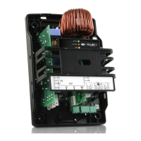
5.10 V/f control for asynchronous motor
In the V/f control, the motor voltage varies linearly with the frequency in the
ow area constant from 0 Hz to the point where the rated voltage is applied
to the motor.
f (Hz)
Un (V)
fn
Fig. 5.d
Key
Un rated voltage fn Rated frequency
The curve can be programmed, by inserting:
1. an increase in starting torque. The boost voltage is applied at frequency 0
for the time set at the “Magnetizing time” parameter, to then drop to zero
in correspondence with the frequency adjustment.
2. a programmable adjustment point, to adapt the application curve better.