ENG
“Power+” +0300050EN - rel. 2.3 - 08.06.2012 18
4. STARTUP
Important: Power+ can pilot various types of compressors with
permanent magnetic motors (PM) brushless BLDC/BLAC sensorless or
asynchronous induction motors. To set the parameters of a particular
compressor, consult the values indicated by CAREL in the document
“Power+: compressors parameters tables”, code +0300051IE, available, also
prior to purchase, upon request.
4.1 Con guration
The con guration of the drive consists in setting the various types of
parameters that regard:
1. the network communication: network address, data communication
baudrate, data communication parity;
2. the selection of the type of motor control;
3. the motor plate data;
4. the motor electric data;
5. motor start-up;
6. the motor control in regenerative functioning mode (load deceleration
with high inertia);
7. the proportional and integral regulation (PI) of the speed.
If the motor electric data (e.g.. resistances, inductance) are not known or are
believed not to re ect the e ective data (for example due to the length of
the motor cable), the Autotuning function can be used. See paragraph 4.5.
Note: once the communication parameters are set and the type of
motor and control selected, the setting of the parameters of points 3...7
depends on the type of motor.
Network communication
Network address
The con guration and the programming of the Power+ drive, as well as
the run/stop commands and the speed reference are managed by a CAREL
pCO control from any BMS (Building Management System) via RS485 serial
connection with ModBus® protocol. The ModBus® network address that can
be set from 1 to 247. This number is made up from the base address that can
be set from the parameter and the address of the 4 dip-switches present on
the drive, which goes from 0 to 15. By changing the base address in steps of
16, the entire interval can be covered.
Communication baudrate/communication parity
Mod. add. Description Def Min Max U.M. R/W
32 Base address 1 1 232 - R/W
121 Dip-switch address - 0 15 - R
120 Network address - 1 247 - R
Tab. 4.a
Important: the drive only reads the network address on switch on or
after a reset control
Dip-switch address Network address
Base address=1
1+0=1
1+15=16
...
232+0=232
232+15=247
0
15
...
0
15
Base address=232
Tab. 4.b
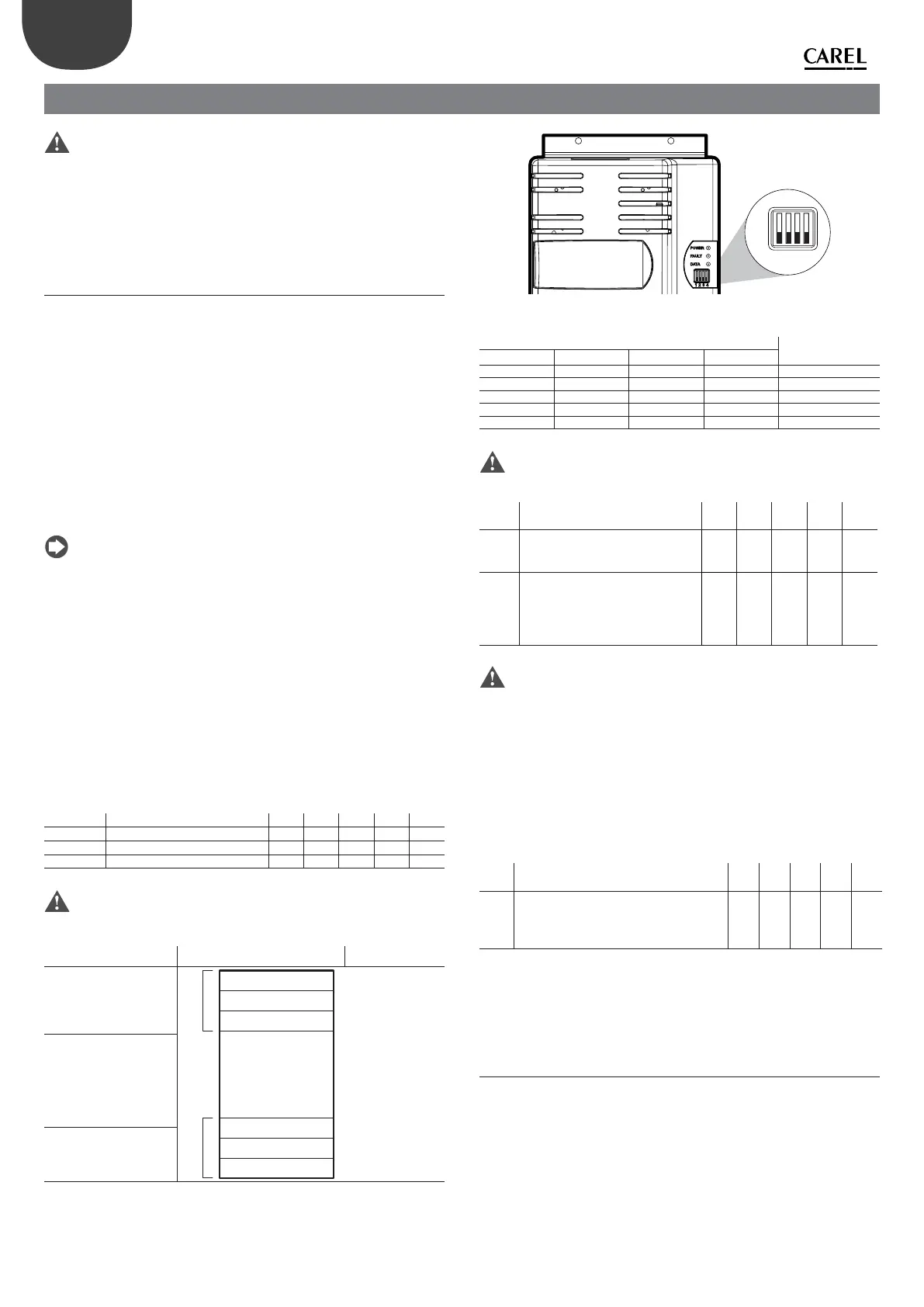
The address of the dip-switches in the drive is set manually as indicated
below.
1
ON
OFF
234
Fig. 4.a
Dip-switch address
Dip-switches Address
Dip-switch
1234
OFF OFF OFF OFF 0
ON OFF OFF OFF 1
OFF ON OFF OFF 2
………… …
ON ON ON ON 15
Tab. 4.c
Important: modify the network address via the dip-switches only with
drive o .
Mod.
add.
Description Def Min Max U.M. R/W
30 Data communication baudrate
0 = 9600 bit/s
1 = 19200 bit/s
101-R/W
31 Data communication parity and
stop bits
0 = none (2 stopbits),
1 = even (1 stopbits),
2 = odd (1 stopbits),
002-R/W
Tab. 4.d
Important: the modi cation of the “Communication baudrate” and
“Communication parity” parameters only becomes e ective on the next
switch on or reset command.
The transmission speed can be selected between 9600 and 19200 bit/s. All
devices connected in the serial network must have the same communication
baudrate and the same data communication parity.
Motor control mode setting
Power+ allows to drive compressors with permanent magnetic motors (PM)
brushless BLDC/BLAC sensorless or asynchronous induction motors. For the
latter it is possible to select between vector or V/f control.
Mod.
add.
Description Def Min Max U.M. R/W
0 Motor control mode
0 = PM brushless motor
1 = asynchronous motor with vector control
2 = asynchronous motor with V/f control
0 0 2 - R/W
Tab. 4.e
Below nd the list of parameters to be set according to the type of motor and
control. Follow the steps described in paragraphs 4.2 or 4.3 or 4.4, on the basis
of the type of motor control selected.
4.2 A - PM motor (brushless)
Motor data plate
Frequency/voltage/rated current/power factor
The base frequency is the frequency at which the base voltage is applied.
Base frequency and base voltage are relative to a generic point in the
voltage/frequency curve speci ed in the motor data sheet. The rated current
is the current at full load. The power factor is not used in this motor, but it is
recommended to set it at 100 (=1.00) for future compatibility.