ENG
“Power+” +0300050EN - rel. 2.3 - 08.06.201223
Mod.
add.
Description Def Min Max U.M. R/W
35 V/f boost voltage 0 0 250
(25.0)
% Motor base
voltage
R/W
36 V/f freq.cy adjustment 0 0 1000
(100.0)
% Motor base
frequency
R/W
37 V/f voltage adjustment 0 0 1000
(100.0)
% Motor base
voltage
R/W
Tab. 5.j
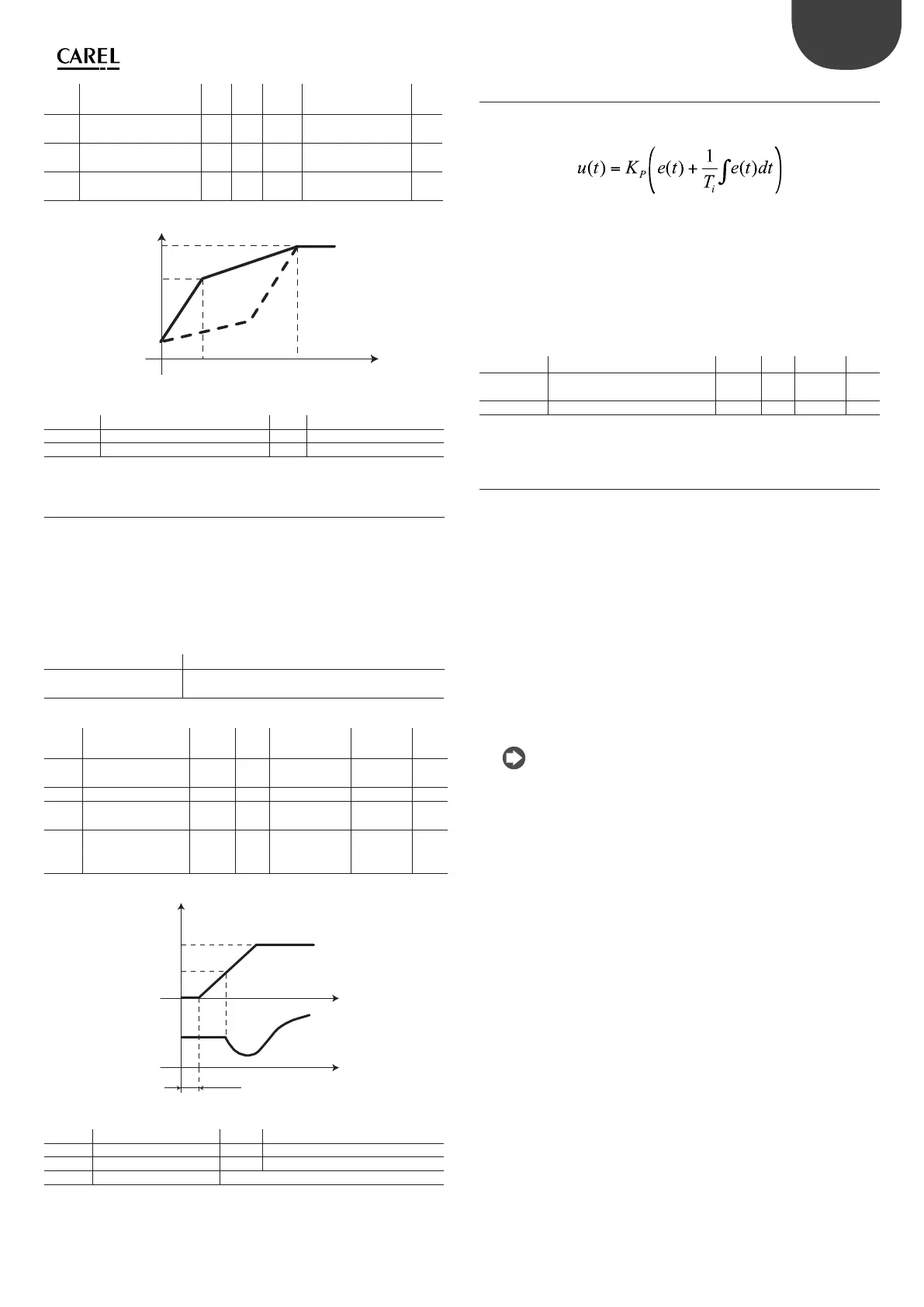
f (Hz)
Un (V)
fn
V_m
f_m
U_boost
Fig. 5.e
Key
fn Rated voltage Un Rated voltage
f_m Intermediate frequency V_m Intermediate voltage
U_boost Voltage boost f Frequency
5.11 Motor control on start-up
To increase torque on start-up, Power+ envisions:
1. for PM brushless motors and for asynchronous motors with vectorial
control, a start-up current for the magnetizing time at frequency 0 and
then to the frequency de ned at the “Maximum frequency for starting
current” parameter. The value of the start-up current is de ned by the
following formulas.
STARTUP CURRENT
PM brushless motor Asynchronous motor with vectorial control
(Motor rated current)*
*(Starting current)
(Magnetizing current)*
*(100+Starting current)
Tab. 5.k
Mod.
add.
Description Def Min Max U.M. R/W
45 Motor magnetizing
current
0 0 Rated output
current
0.1A R/W
51 Magnetizing time 100 0 30000 0.001s R/W
57 Starting current 200
(20.0%)
0 1000
(100.0%)
0.1% R/W
58 Max frequency for
starting current
0 0 1000
(100.0%)
0.1%
Motor base
frequency
R/W
Tab. 5.l
f_set
t
I_start
t_magn
0
0
f_start
f(Hz)
t
I
Fig. 5.f
Key
f_set Frequency set point f_start Max frequency for starting current
t_magn Magnetizing time I_start Start-up current
t Time f Frequency
I Current
2. for asynchronous motor with V/f control: see the “V/f control for
asynchronous motor” paragraph.
5.12 PI parameters
Speed regulation takes place via a PI type control, which in its simplest form
is characterised by the following law:
Note that the control is calculated as the sum of the two separate
contributions, proportional and integral:
• the proportional action varies the control action proportionally to the
error. Therefore the greater the value of Kp (proportional gain) the faster
will be the response speed. The proportional action, alone, does not allow
the set point to be reached.
• the integral action varies the control action proportionally to the area of
the error. The lower the Ti (integral time) value, the more energetic the
control action. Moreover, the PI control tends to annul the error.
Mod. add. Description Def Min Max U.M.
55 Speed loop: Kp 250
(25.0)
0 2000
(200.0)
0.1%
56 Speed loop: Ti 500 1 1000 ms
Tab. 5.m
5.13 Commands
1. Run/stop:
• bit0: run control (Run=1) and stop control (stop=0) of the motor;
• bit1: setting the direction of rotation, clockwise (0) or anti-clockwise
(1). In order to have anti-clockwise rotation this must be previously
enabled with the “Reverse speed enable” parameter.
2. Reset:
• bit0: allows to cancel the alarms present in the alarms queue and to
update the address communication, data communication parity and
communication baudrate parameters. For example, the command
must be given after modi cation of the dip-switches in order to set
the network address.
• bit1: allows to set the parameters at factory value (default). When the
operation has taken place, the “Parameter default” alarm occurs. See
the alarms table.
• bit2: reset ag check drive switch on and switch o (see speed register,
bit2)
Note: the resets take place on transition of the respective bit from
zero to one and therefore it is necessary to take the bit at zero in order to
allow a successive reset action.
3. Frequency set point it is the set point that the motor must reach
following the “Run” command; the direction of rotation is given by the
bit1 of the Run/Stop command.
4. Autotuning: the command is given after having set the motor plate
data, if electric data is not available (resistances, inductance) of the
speci c motor. When autotuning has ended, the parameter 104 goes
automatically back to zero. See the chapter 4 “STARTUP”.