ENG
“Power+” +0300050EN - rel. 2.3 - 08.06.20129
3. INSTALLATION
Important: avoid installing the drive in environments with the
following characteristics:
• relative humidity higher than 95% or with condensation;
• strong vibrations or knocks;
• exposure to water sprays;
• exposure to aggressive and polluting atmospheres (e.g.: sulphur and
ammonia fumes, saline mist, smoke) to avoid corrosion and/or oxidation;
• strong magnetic and/or radio frequency interference (thus avoid
installation near transmitting antennae);
• exposure of the drive to direct sunlight and the elements in general.
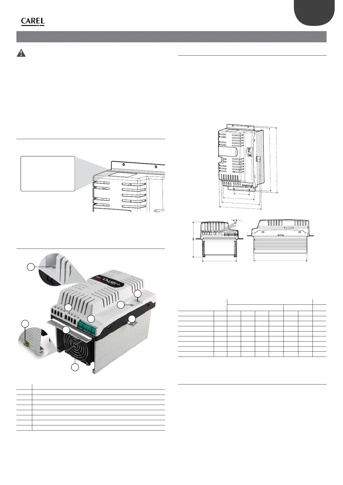
3.1 Identi cation
Power+ is identi ed by a rating plate located on the top of the device, which
describes the code, serial number, production date and revision number.
PSD0********
S/N
Input:
Output:
Date:
Rev:
Fig. 3.a
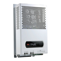
3.2 Structure
E
C
C
D
H
A
B
F
G
Fig. 3.b
Ref. Description
A Terminal block for power connections
B Terminal block for control connections
C Fastening brackets
D Cooling fan
E PE
F Microswitches for setting the network address
G Operating status LED
H Terminal block for PFC coil connection or optional DC choke
Tab. 3.a
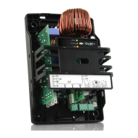
3.3 Dimensions
The overall dimensions of the drive vary based on the size of the heat sink (size
1 and size 2 for models with forced air cooled nned heatsink and size 3 for
Coldplate models) and the type of assembly (panel or with heat sink outside
of the panel, see the paragraph on “Drilling and assembly”), as the position
of the fastening brackets a ects the total height. The side brackets are only
needed for assembly with the heat sink outside of the panel. For single-phase
models, the dimensions increase because the coil for power factor control
circuit (PFC) also needs to be connected. For three-phase models space may
also be required for a DC choke for limiting the power factor. All the brackets
have a 5.5 mm diameter hole.
80
163,8
C
B
A
125
E
75
7,5
D
240,8
Fig. 3.c
DIMENSIONS (mm)
Assembly
Weight
Heat sink outside panel Panel (kg)
Model / size E A B C D A B
PSD0012200 / 1 77 299,2 289,2 192,3 202,3 279,3 269,3 3,3
PSD0016200 / 2 107,9 299,2 289,2 192,3 202,3 279,3 269,3 4,0
PSD0014400 / 1 77 299,2 289,2 192,3 202,3 279,3 269,3 3,6
PSD0022400 / 2 107,9 299,2 289,2 192,3 202,3 279,3 269,3 4,4
PSD00122A0 / 3 12 299,2 289,2 192,3 202,3 - - 2,5
PSD00162A0 / 3 12 299,2 289,2 192,3 202,3 - - 2,5
PSD00144A0 / 3 12 299,2 289,2 192,3 202,3 - - 2,7
PSD00224A0 / 3 12 299,2 289,2 192,3 202,3 - - 2,8
Tab. 3.b
3.4 Drilling and assembly
For installation with the heat sink outside of the panel, make a hole with
dimensions of the dashed rectangle, where the heat sink will be tted, and
holes for fastening the brackets. These are inserted in the slots between the
heat sink and the plastic cover. For panel installation, only use the top and
bottom brackets, which are inserted in the slots above and below the heat
sink.