ENG
“Power+” +0300050EN - rel. 2.3 - 08.06.201225
6. PROTECTIONS
Protections functions exist that intervene to prevent:
1. mechanical resonances;
2. drive overtemperature.
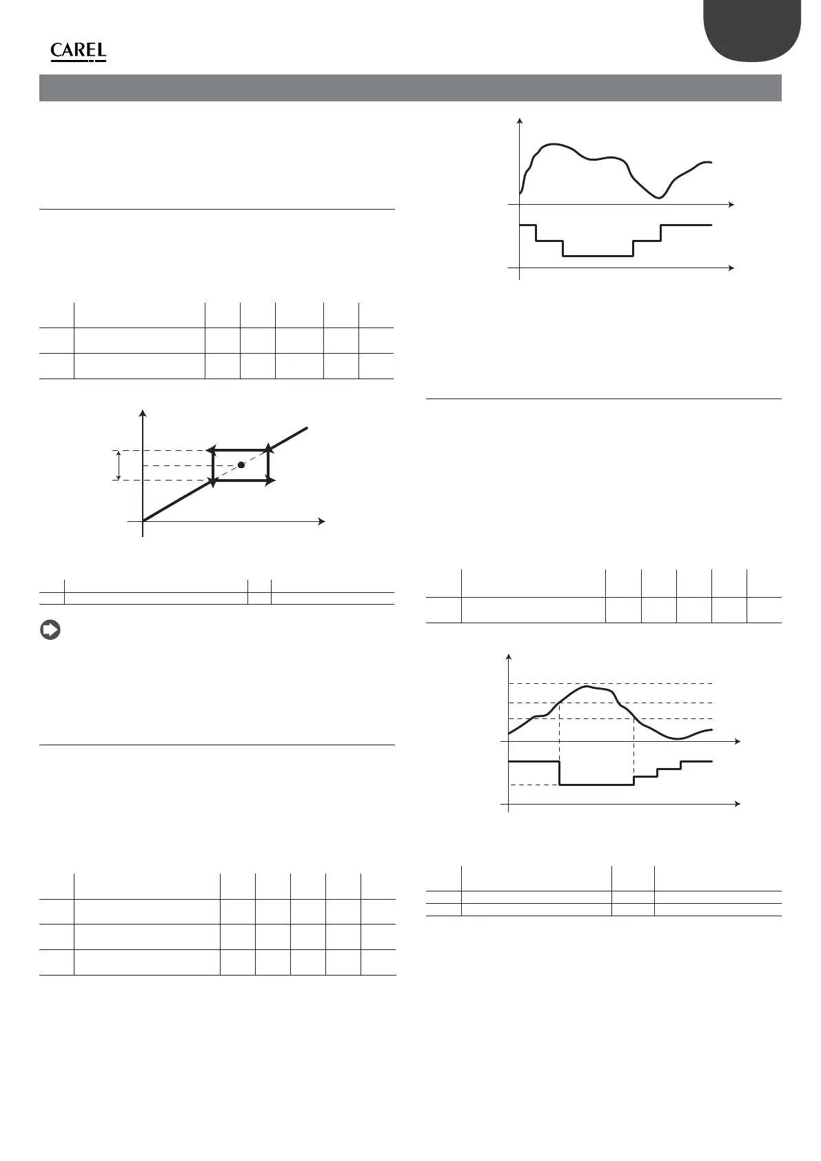
6.1 Skip frequency
It may be necessary to avoid particular frequencies in some systems due
to mechanical resonance problems. Using the following parameters it is
possible to x the limits of the frequency area to be avoided for the frequency
set point. If the frequency set point assumes a value within the area, the
e ective set point is blocked at values fc-B/2 or fc+B/2, depending whether
the frequency is increasing or decreasing.
Mod.
add.
Description Def Min Max U.M. R/W
10 Skip frequency: set 0 0 5000
(500.0Hz)
0.1Hz R/W
11 Skip frequency: band 0 0 5000
(500.0Hz)
0.1Hz R/W
Tab. 6.a
B
fc
f
t
Fig. 6.a
Key
fc Skip frequency: set B Skip frequency: band
t Time f Frequency
Note: if the set point is outside the area de ned by the set and the
band, traversing the prohibited area takes place with normal acceleration
and deceleration.
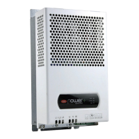
6.2 Automatic reduction of the switching
frequency
On increasing switching frequency, motor noise decreases, but the heat to
be dissipated increases and therefore, also the temperature of the drive. The
switching frequency set is used on start-up and can be gradually decreased
automatically if the temperature of the drive reaches high values, in a way
to prevent the drive overtemperature alarm. If successively the temperature
of the drive is within the typical values, the switching frequency gradually
returns to the initial value. Among the reading-only variables, it is possible to
display the e ective switching frequency.
Mod.
add.
Description Def Min Max U.M. R/W
24 Switching frequency
0 = 4kHz; 1 = 6kHz; 2 = 8kHz
002-R/W
25 Switching frequency derating
0/1 = no/yes
001-R/W
124 Operating switching frequency
0=4kHz, 1=6Hz, 2=8kHz
002-R
Tab. 6.b
f_switch
t
t
T_drive
Fig. 6.b
Key
T_drive Drive temperature t time
f_switch switching frequency
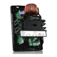
6.3 Automatic reduction of motor speed
It is possible to prevent the drive overtemperature alarm also using the
automatic motor speed reduction function. Decreasing motor speed
corresponds to decreasing the output power of the drive and therefore
the heat to be dissipated. See the following gure. To activate the function,
set the “Speed reduction mode” parameter at a value >0, which becomes
the di erential (DT) in order to determine the temperature threshold (T_
th-DT). When this is exceeded, the speed set point is forced to minimum,
corresponding to the “Minimum output frequency” parameter. If after a
certain period of time, the temperature of the drive drops below the value
T_th-2DT, the set point gradually returns to the requested value. If the
di erential is set at zero, the function is disabled.
Mod.
add.
Description Def Min Max U.M. R/W
9 Speed derating mode
0 = function disabled
0 0 10 °C R/W
Tab. 6.c
f (Hz)
f_min
f_set
t
t
T_drive
T_th
T_th-DT
T_th-2DT
Fig. 6.c
Legenda
t Time DT Di erential for automatic
speed decrease function
f_set Frequency set point t_drive Drive temperature
T_th Over-heating alarm threshold f_min Out frequency min