ENG
“Power+” +0300050EN - rel. 2.3 - 08.06.2012 26
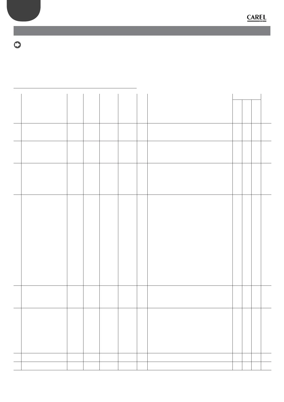
7. PARAMETERS TABLE
Note:
• the values of some parameters are expressed in tenths, hundredths,
thousandths of the unit of measurement. For commodity, in this case the
equivalent corresponding value in the standard unit of measurement is
indicated at the side in brackets;
• Y/N = YES/NO
• all parameters and commands are accessible in reading and writing (R/W),
the status variables are reading only (R). The identi cation is by address. If
register identi cation is to be used, use the following formula: register =
address+1
7.1 Parameters table
Mod. add.
Parameter Def Min Max U.M. R/W Description Applicable for
Can’t be modi ed if
drive is in RUN
PM AC
vect.
AC
V/f
0 Motor control mode 0 0 2 - R/W Sets the type of motor and control.
0 = PM brushless motor
1 = asynchronous motor with vector control
2 = asynchronous motor with V/f control
YYY Y
1 Motor base frequency 500
(50.0Hz)
250
(25.0Hz)
5000
(500.0Hz)
0.1Hz R/W Sets the motor base frequency (electric). For
asynchronous motors (both vector and V/f control) the
value can normally be found on the motor technical
plate. For motors with permanent magnets (PM) it is
suggested to set it at values indicated by CAREL.
YYY Y
2 Motor base voltage 230/400 25 250/500 V R/W Sets the phase-phase rated voltage (corresponding to
the motor base frequency). For asynchronous motors
(both vector and V/f control) the value can normally
be found on the motor technical plate (depending on
the type of triangle/delta connection). For motors with
permanent magnets (PM) it is suggested to set it at
values indicated by CAREL.
YYY Y
3 Motor rated current Drive
rated
output
current
Model
depen
dent
(*)
Drive rated
output
current
0.1A R/W Sets the motor rated current. It is also the reference
for motor overload protection (I*T “current*time”
up to 150% of the rated current for 1 minute). For
asynchronous motors (both vector and V/f control) the
value can normally be found on the motor technical
plate. For motors with permanent magnets (PM) it is
suggested to set it at maximum motor current (normally
corresponding to maximum electric frequency). For
asynchronous motors with V/f control, only set the
current threshold for overload protection. For PM
brushless and asynchronous motors with vector control,
the parameter establishes the maximum supplied
current value. If to turn at a given speed, the motor
requires a higher current than that set here, the drive
limits the current with consequent speed reduction to a
value consistent with the current supplied.
(*) Min:
PSD0***2*0**: 26(2.6A);
PSD0*144*0**: 36(3.6A);
PSD0*224*0**: 56(5.6A)
YYY Y
4 Motor power factor (cos()) 100
(1.00)
0/50
(0.5)
100
(1.00)
- R/W Sets the motor power factor (cos()). For motors with
permanent magnets (PM) it is suggested that the value
is set at 100 (1.00). For asynchronous motors with vector
control, the value can usually be found on the motor
technical plate, set at 0 if the power factor is unknown.
NYN Y
5 maximum output current 1000
(100.0%)
0 2000
(200.0%)
0.1%
Motor
rated
current
R/W If the control envisions, it is possible to supply the
motor with current that can reach double the rated one,
considering that the resulting current will be limited
by the maximum value that can be supplied by the
drive. A larger current than that supplied by the “Rated
current” parameter can be applied for a limited period
of time, after which the “Motor overload” alarm occurs.
The threshold beyond which the alarm is activated
corresponds to functioning at 150% of the rated current
for 1 minute.
YYNN
6 Maximum output frequency 0 0 5000
(500.0Hz)
0.1Hz R/W Sets the drive maximum output frequency (electric) Y Y Y N
7 Minimum output frequency 0 0 5000
(500.0Hz)
0.1Hz R/W Sets the drive minimum output frequency (electric) Y Y Y N