ENG
“Power+” +0300050EN - rel. 2.3 - 08.06.2012 12
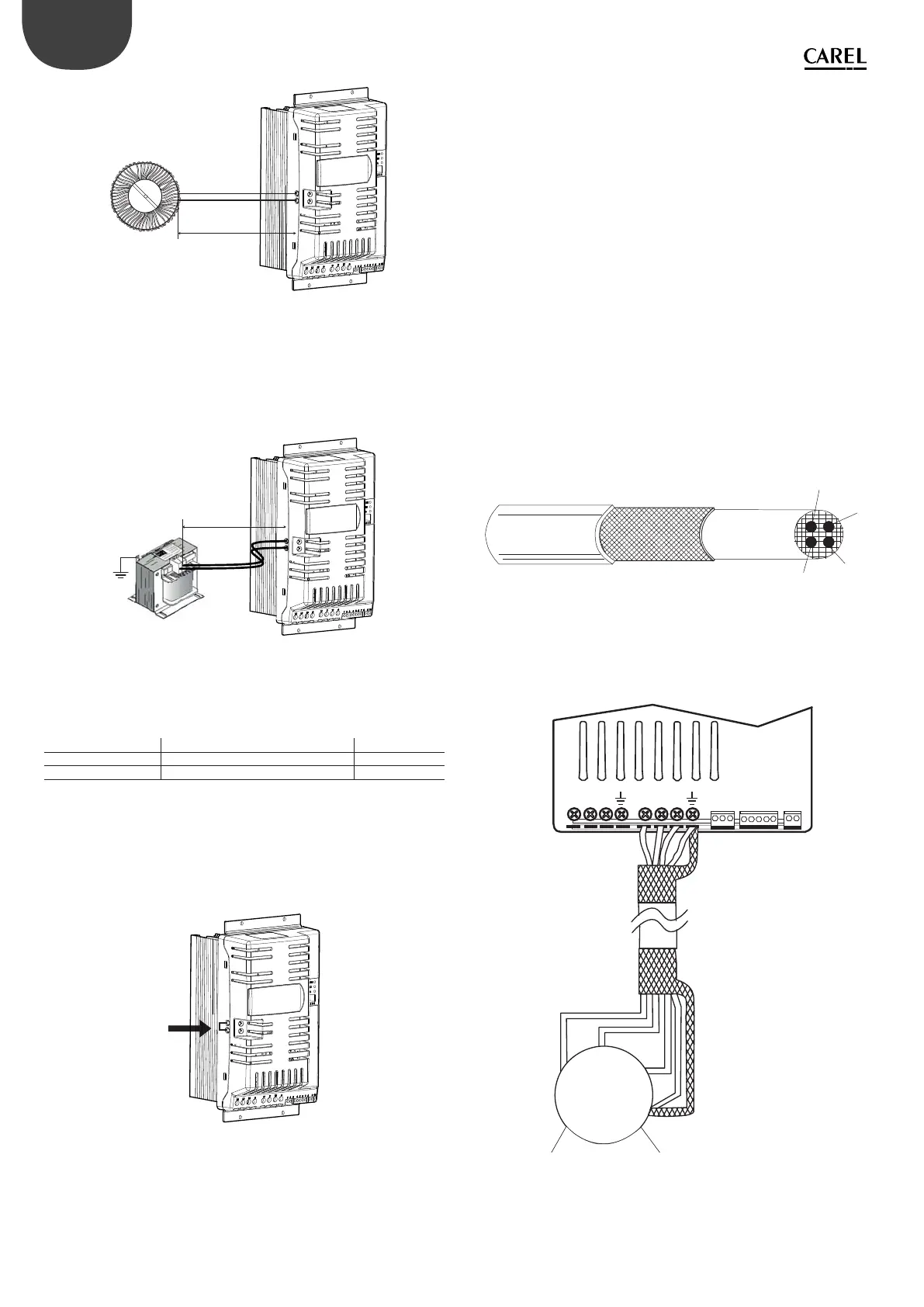
Induttanza PFC
solo per modello monofase
PFC coil
for single-phase model only
C1
C2
200mm
Fig. 3.i
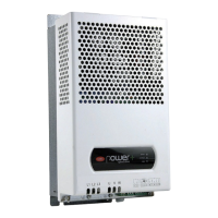
Models with 380/480 Vac three-phase power supply
There are two possible cases:
1. if compliance with EN61000-3-12 is required:
connect the optional DC choke to terminals C1 and C2.
Connect the DC choke to earth using the relevant metal terminal
C1
C2
2m max
Fig. 3.j
To connect the DC choke to terminals C1 and C2, use a cable that is the same
size as the power cable. The maximum length of the cable must be 2 m.
The DC choke used depends on the size of the drive:
DC choke code to be installed on Power+ drive type
PSACH10000 PSD0014400, PSD00144A0 3mH, 20A
PSACH10100 PSD0022400, PSD00224A0 2mH, 25A
Tab. 3.d
See paragraph 3.13 for the dimensions of the DC choke
2. if compliance with EN61000-3-12 is not required:
jumper terminals C1 and C2 (the drive leaves the factory with C1 and C2
jumpered).
C1
C2
Fig. 3.k
Earth leakage current
As for all inverter devices, earth leakage current greater than 3,5mA may
occur. The drive is designed to produce the minimum possible leakage
current. The current depends on the length and the type of motor cable, the
e ective switching frequency, the type of earth connection used and the
type of RFI lter installed.
If a residual-current circuit breaker (RCCB) is to be used, the following
conditions apply:
• it must be a type B device (suitable to protect the equipment against
leakage current with a DC component);
• Individual RCCBs should be used for each drive.
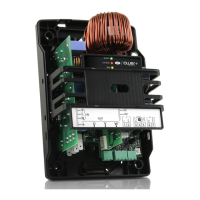
Motor
Connect the motor power cable: use four-wire cable, the impedance of the
earth wire must be less than or equal to the impedance of the phase wires.
For the size and maximum length of the cable according to the model, see
the table in paragraph 9.1. To ensure conformity to the EMC directive, use
shielded cable with the shield that covers at least 85% of the surface of the
cable, with low impedance for high frequency signals. The cable can also be
laid in steel and copper cableways.
U
V
W
PE
MOTOR CABLE
Fig. 3.l
The shield is connected to both ends of the cable: the drive earth terminal
should be connected by twisting the shield. The twisted part must be left as
short as possible, and the length must not exceed ve times the width. Earth
the motor directly using the drive earth terminal.
L1/L L2/N
L3
U
VW
123 456
78
910
U
V
W
PE
.
Fig. 3.m
Connect the motor phases so as to ensure the required direction of rotation:
to reverse direction, swap over two of U, V, W wires as indicated in the
following gures.