ENG
“Power+” +0300050EN - rel. 2.3 - 08.06.201213
M
UVW
UVW
M
L1/LL2/N L3 U VW
L1/LL2/N L3 U VW
Fig. 3.n
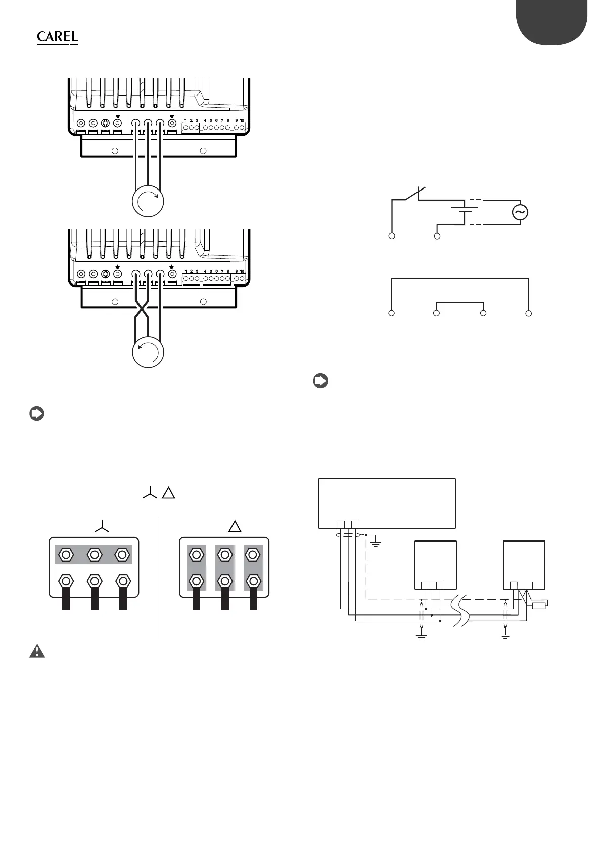
Note: Most general purpose asynchronous motors are wound for
operation on dual voltage supplies. This is indicated on the nameplate of
the motor. This operational voltage is normally selected when installing the
motor by selecting either Star or Delta connection. Star always gives the
higher of the two voltage ratings. Typical ratings are:
/
400V/230V
690V/400V
Star Delta
UVW
UVW
Fig. 3.o Fig. 3.p
Important: do not turn on or OFF a switch between the drive and the
motor when the drive is running.
Motor protector
Connect a PTC thermistor motor protector to terminals 4 and 5: use a cable
with a minimum cross-section of 1 mm2; alternatively, a Klixon thermostat
can be connected (see the general connection diagram). The PTC thermistor
must be selected so that at activation temperature the resistance is > 2600 .
Safety digital input
Connect the “Safety Torque O ” digital input to a safety device (for example,
a maximum pressure switch) with normally closed voltage-free contact, in
series with an external 24 Vac/24 Vdc voltage source, without needing to
observe the polarity for direct current (ref. A). When the contact is open, the
drive stops operating, bypassing the software control. If the Safety Torque
O function is not used, the input must be connected to the auxiliary 24
Vdc available on the terminal block, so as to enable correct operation of the
drive (ref. B).
Dispositivo di sicurezza NC
NC Safety device
24 Vdc
78
24 Vac
A
56 78
B
Fig. 3.q
Note: IEC61508 standard requires that the power supply applied to the
safety input is isolated from the drive.
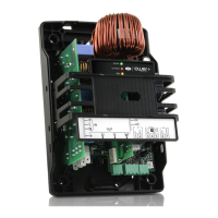
Serial network connection
For the serial connection use a three-wire shielded cable. For large networks,
install a 120 ohm ¼. W resistor between terminals 2 and 3 on the last drive or
device connected, to avoid possible communication problems.
pCO
/ building management system
RS485
Schermo
Shield
R = 120 ohm
Power +
123
GND
Tx/Rx+
Tx/Rx-
0 V
Tx/Rx+
Tx/Rx-
Power +
123
0 V
Tx/Rx+
Tx/Rx-
Fig. 3.r