10
powerSplit manual - cod. +030220320 rel. 1.1 - 09/12/02
3. Installazione
Installazione e collegamenti
Avvertenze generali - ambienti di destinazione e collegamenti
Le seguenti condizioni soddisfano una corretta installazione:
1. evitare il montaggio dello strumento negli ambienti che presentano:
ampie e rapide fluttuazioni della temperatura ambiente, umidità
relativa maggiore dell’80%, esposizione a getti d’acqua diretti
sotto pressione, alte interferenze elettromagnetiche e/o
radiofrequenze (per es. di antenne trasmittenti);
2. utilizzare capicorda adatti ai morsetti in uso. Allentare ciascuna vite
ed inserirvi i capicorda, quindi serrare le viti. Ad operazione ultimata
tirare leggermente i cavi per verificarne il corretto serraggio;
3. separare quanto più possibile i cavi delle sonde e degli ingressi digitali
dai cavi dei carichi induttivi e di potenza per evitare possibili disturbi
elettromagnetici. Non inserire mai nelle stesse canaline (comprese
quelle dei cavi elettrici) cavi di potenza e cavi delle sonde. Evitare
che i cavi delle sonde siano installati nelle immediate vicinanze di
dispositivi di potenza (contattori, interruttori magnetotermici o simili);
4. ridurre il più possibile il percorso dei cavi dei sensori ed evitare che
compiano percorsi a spirale che racchiudano dispositivi di potenza.
Per prolungare i cavi delle sonde, usare cavi con sezione minima di
almeno 0,5 mm
2
;
Precauzioni di installazione:
• i cavi di collegamento devono garantire l'isolamento almeno fino a 90 ˚C
• per il montaggio scheda utilizzare solo distanziali plastici e prevedere
almeno 10 mm rispetto a parti conduttive vicine alle connessioni
della scheda
• i collegamenti sonde e ingressi digitali devono risultare inferiori a 30
m di sistanza, adottare le adeguate misure di separazione dei cavi
per il rispetto delle normative di immunità
• bloccare adeguatamente i cavi di connessione delle uscite per evitare
contatti con componenti in bassissima tensione.
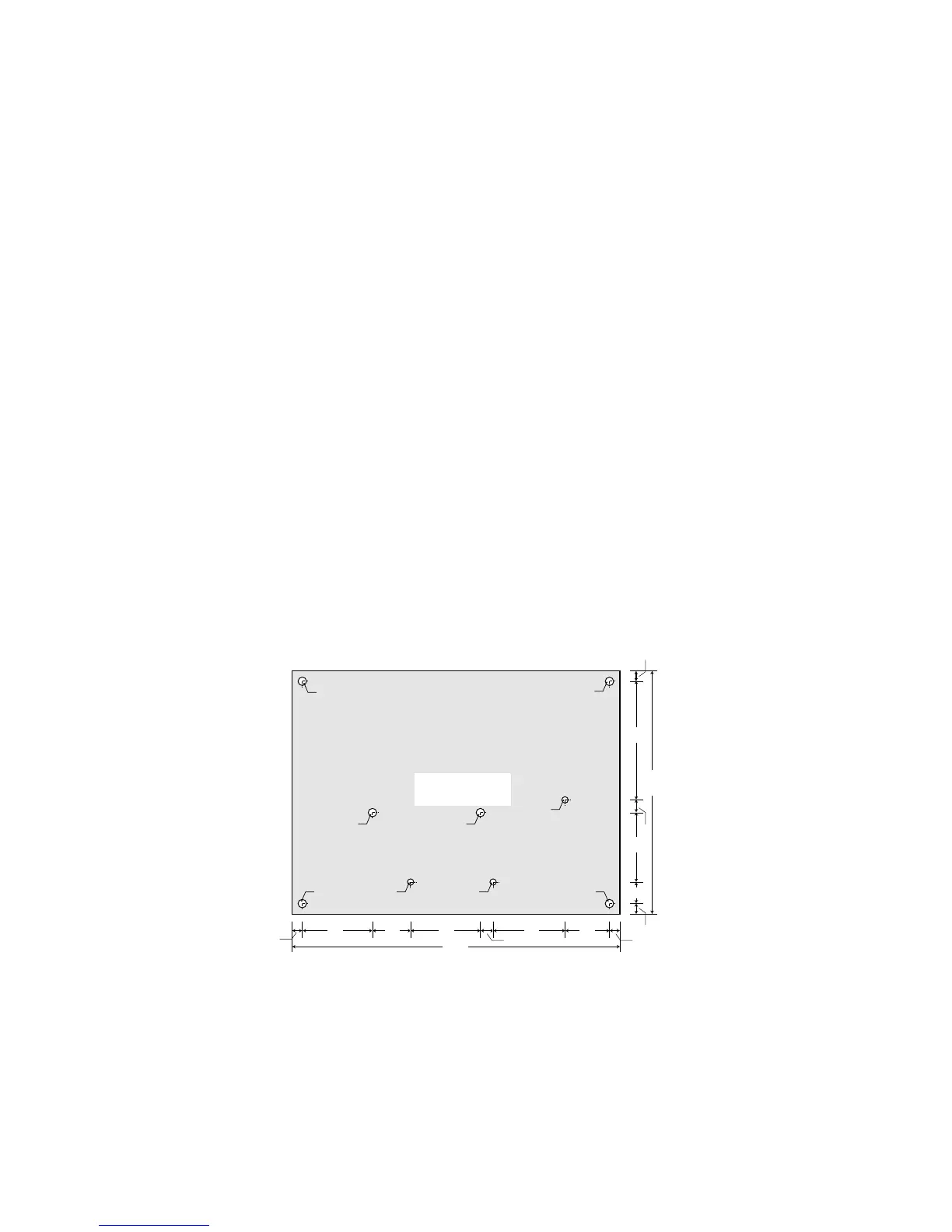
3.1 Dimensioni e montaggio
Il montaggio del PSB è a
retroquadro mediante distanziali
plastici di aggancio della scheda;
è possibile utilizzare anche
torrette metalliche, ma in tal caso
si devono verificare le distanze
di isolamento per la conformità
alle normative di sicurezza.
Nota:
Fori (A) diam. 4 mm per fissaggio
scheda mediante distanziali plastici.
Punti (B) di appoggio per
sostegno scheda inserimento con-
nessioni FASTON.
Distanziali e particolari di
appoggio scheda forniti da Carel
assieme al controllo.
3. Installation
Installation and connections
General warnings – installation and connection environments
The following conditions represent the correct installation:
1. avoid installing the instrument in environments featuring: wide and
rapid fluctuations in ambient temperature, relative humidity over
80%, exposure to direct jets of pressurised water, high levels
of electromagnetic and/or radio-frequency interference
(e.g. transmitting antennae);
2. use cable terminals that are suitable for the terminals being used.
Loosen each screw and insert the cable ends, then tighten the
screws. Once this operation has been completed, lightly tug the
cables to check that they are sufficiently tight;
3. separate as much as possible the probe and digital input cables
from cables carrying inductive loads and power cables, to avoid any
electromagnetic disturbance. Never lay power cables and
probe cables in the same channels (including those for the electrical
cables). Do not install the probe cables in the immediate vicinity of
power devices (contactors, thermal overload switches or the like);
4. reduce the path of the sensor cables as much as possible and avoid
laying spiral paths around power devices.To extend the probe
cables, use cables with a minimum cross-section of at least 0.5 mm
2
;
Precautions for installation:
• the connection cables must guarantee insulation to at least 90˚C
• when mounting the board, only use plastic spacers and leave a
distance of at least 10mm from the conducting parts near the board
connections
• the probe and digital input connections must be located at a distance
of less than 30m, adopt adequate measures for separating the
cables, so as to ensure compliance with the immunity standards
• suitably clamp the output connection cables so as to avoid contact
with low voltage components.
3.1 Dimensions and mounting
The PSB is mounted at the rear
of the panel, using plastic
spacers for fastening the board;
metal turrets can also be used,
but in this case the insulation
distance must be checked for
compliance with the safety
standards.
Notes:
(A) 4 mm diam. holes for
fastening the board using
plastic spacers.
(B) Board supports for the
FASTON connections.
Spacers and board supports
supplied by Carel together with
the controller.
 Loading...