58
ENG
UltraCella +0300083EN - rel. 1.5 - 07.02.2015
8. SIGNALS AND ALARMS
8.1 Signalling
The signals are messages that appear on the display to notify the user
regarding the performance of control procedures (such as defrost) or
confi rmation of controls from keyboard.
Code Description
--- It appears at controller start-up
--- Probe not enabled
Parameters categories
Pro Probes
CtL Control
CMP Compressor
dEF Defrost
ALM Alarm
Fan Fan
CnF Confi guration
HcP HACCP
rtc Clock
rcP Recipes
Evd EVD Evo
3PH Three phases Module 3PH
Messages that appear during navigation
PAS Password
HA HACCP alarm, HA type
HF HACCP alarm, HF type
rES Reset alarms with manual reset
Reset HACCP alarms
Reset temperature monitoring
cc Continuous cycle
Ed1 Defrost on evaporator 1 ended by time-out
Ed2 Defrost on evaporator 2 ended by time-out
On Switch ON
OFF Switch OFF
AUX Auxiliary output switch on request
rEc Temperature registration
no Operation not executed
uPd Parameters upload
dnL Parameters download
bni Menu parameters set (bn)
r01…r10 Recipe 1…10
MAX Maximum temperature read
MIN Minimum temperature read
Op Open
cLo Closed
EXT Exit menu
Hcr Reset HACCP alarms
VEr Software release
LOG Temperature recorded download
ALG Alarms recorded download
Tab. 8.a
8.2 Alarms
There are two types of alarms:
• system alarms: e.g. Eeprom alarms, communication (interrupted)
alarms, HACCP, high (HI) and low (LO) temperature alarms;
• control alarms: e.g. pump down ended by time-out (Pd), low pressure
(LP).
The alarm for damaged data inside EE/EF memory generates control
block. The auxiliary digital outputs AUX1, AUX2 can be confi gured to
signal the alarm status, as normally energised or normally de-energised.
See chapter 5. The control indicates the alarms triggered due to faults in
the control itself, in the probes or in the network communication. You can
also activate an alarm from external contact, immediate type. See chapter
4. On the display the message “IA” appears and at the same time the bell
icon blinks and the buzzer activates. If more errors occur, they will appear
in sequence on the display.
Example: display after alarms rE and E0.
1 21 2
1 21 2
1 21 2
Note: in order to deactivate the buzzer and the relay alarm press
the Alarm key
Note: the fi gures refer to the screens on models with single row
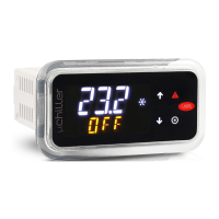
display, P/Ns WB000S*. In models with two rows, P/Ns WB000D*,
the display shows the alarm messages on the second row.
8.3 Reset alarms
Alarms with automatic reset automatically reset when the cause that
generated them, for example, after the replacement of a faulty probe,
at the end of the alarm for high temperature, etc. For those with manual
reset it is necessary to fi rst remove the cause that generated them, and
then press the Alarm button for entire restore.
Example: display and manual restore alarm CHt (condenser high
temperature)
1 21 2
1 21 2
1 21 2
1 21 2
1 21 2
Note: the fi gures refer to the screens on models with single row
display, P/Ns WB000S*. In models with two rows, P/Ns WB000D*,
the display shows the alarm messages on the second row
8.4 HACCP alarms and display
In order to activate monitoring see par 8.6
(HACCP = Hazard Analysis and Critical Control Point).
HACCP can only be activated on the controllers with the RTC option fi tted,
and allows control of the operating temperature and the recording of any
anomalies due to power failures or increases in the operating temperature
due to various causes (breakages, severe operating conditions, operator
errors, etc…). There are two types of HACCP events:
• HA alarms, high temperature during operation;
• HF alarms, high temperature after power black out.
The alarm causes the blinking of HACCP icon, the display of the relative
alarm code on the display, storage of the alarm and activation of the
buzzer.
Example: display after HF error and restore of the alarm condition:
1 21 2
1 21 2
 Loading...
