Page | 21
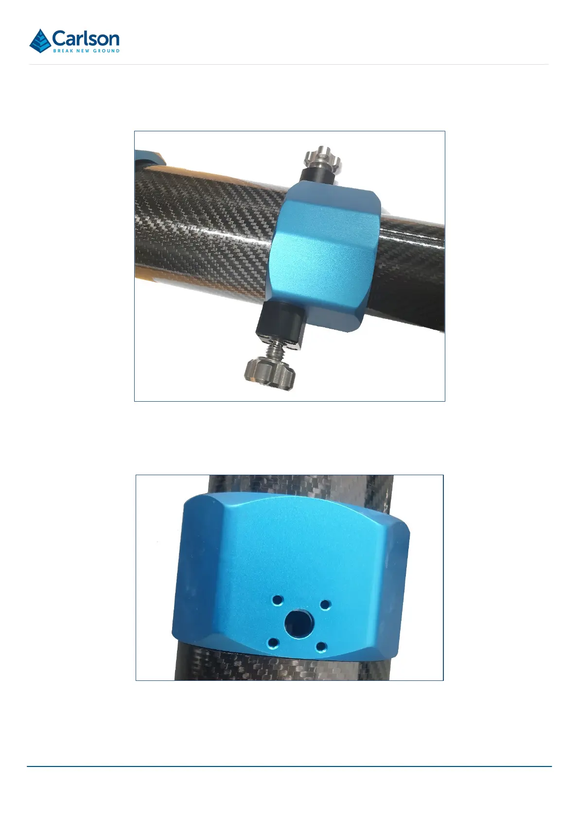
Tighten each M4x20 screw to 2.6Nm so that the captive screw base is securely attached to the boom joint.
For optimum stability, fit a screw base to both sides of each joint.
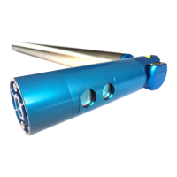
To lock the boom sections in place during operations, extend the carbon fibre section fully so that a hole in the tube
is lined up with the hole in the blue metal joint (note: the hole in the tube in Figure 23 is shown with the captive
screw base removed). The sections may need twisting slightly to allow them to fully extend.
Screw down the captive screw to lock the section in place.
Figure 22 Captive screw bases attached to both sides of the boom joint
Figure 23 Aligning holes in the carbon fibre with hole in the blue boom joint