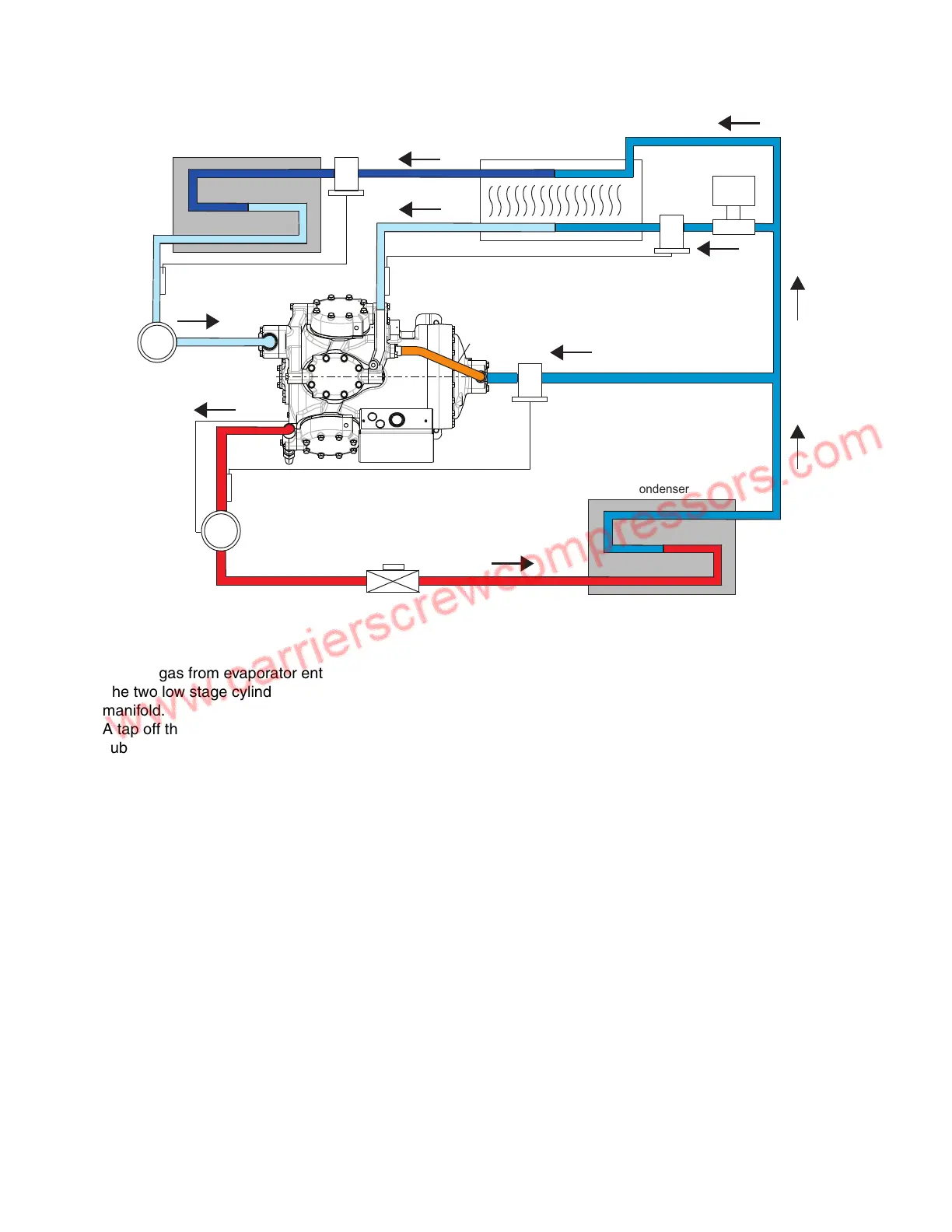
Fig. 1 — Single Compressor System
System Operation:
1. Suction gas from evaporator enters compressor suction manifold.
2. The two low stage cylinder banks compress refrigerant to intermediate pressure and flow to the intermediate
manifold.
3. A tap off the main liquid line directly expands refrigerant at condensing pressure to interstage pressure in the
subcooler.
4. Liquid on the way to the evaporator passes through the heat exchanger and is subcooled.
5. Cool suction gas at interstage pressure flows from the heat exchanger to the intermediate manifold (econo-
mizer port) where it is mixed with the refrigerant leaving the low stage cylinders. This mixing desuperheats the
intermediate stage refrigerant.
6. Desuperheated refrigerant (at intermediate pressure) flows to motor compartment and then through internal
passages to high stage cylinder block.
7. High stage cylinder compresses refrigerant and discharge to condenser.
 Loading...


