4.
3.
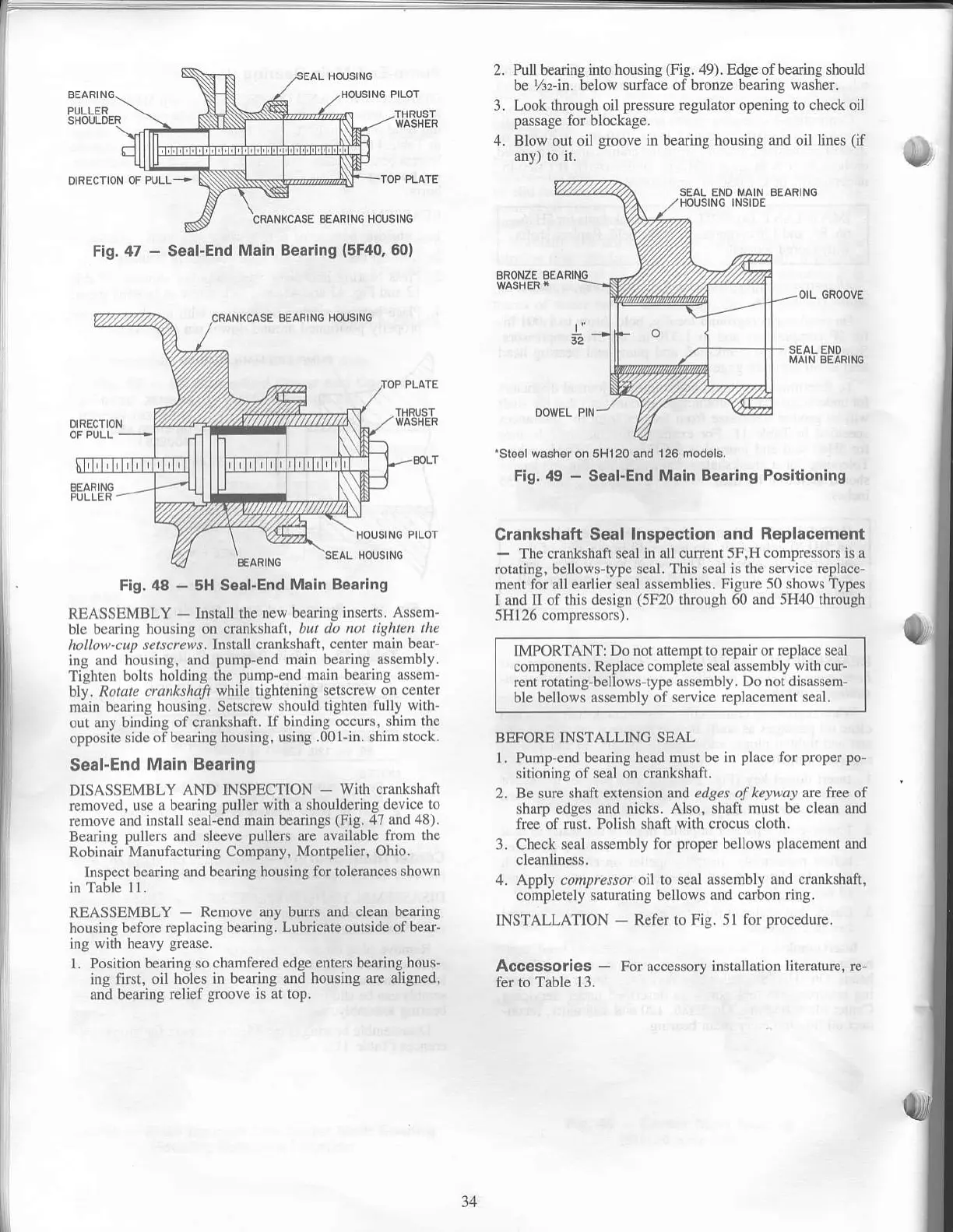
Pull beiring into
housing
(Fig.
49). Edge ofbearing should
be
%r-in. below surface of bronze bearing washer.
Look tlmugh oil
pressure
regulator opening
to
check oil
passage for blockage.
Blow out oil
groove
in bearing housing and oil lines
(if
any) to it.
SEAI. ENO iIAIN BEAiIiiIG
HOUSING INSIDE
BRONZE BE
KCASE BEAFIN6
HOUSING
SEAL ENO
Fig,
,18
-
5H Soal-End
Main Bearing
REASSEMBLY
-
Install the
new bearing inserts.
Assem-
ble bearing housing on .ftnkshafr,
but do not
tiShten the
hollow-cuD setscrcrrs. lnstall crankshaft. center
main bear-
ing and
liousing, and
pump-end main bearing assemoty.
Tishten
bolls holding the
pump-end
main bearing
assem-
bly. Rotate crunkthall
while
lightening
setscrew on center
main bearing
housing. Setscrew should
tighten fuUy
wirh-
our anr bindins
of crankshaft. lf
bindins occurs, .hirn the
opposiie
'ide oibering housin8.
using .011-in. shim
stock.
Seal-End
Main Bearing
DISASSEMBLY AND INSPECTION
-
With crankshaft
removed.
u'e a bearing
puller with
a shoul(hring
device to
remore and install .ealie'nd main bearings
(Fig.47
and
48,.
Bearing
pullers
and sleeve
pullers
are available from
the
Robinair Manufacturing Company,
Montpelier, Ohio.
Inspect bearing
and b€aring housing for tolerances
shown
in Table
11.
REASSEMBLY
-
Remove any burN and clean bearing
housing before
replacing bearing. Lubricate outside
of bear-
ing with heavy
grease.
l Position bearing so
chamfered edge enters bearing hous-
jng
firsi, oil
holes in bearing and housing
are aligned,
and
bearing
relief
groove
is at top.
'S166lwash*
on 5H120 and 126 models.
Fig, 49
-
Sgal.End
Moin Boaring Positioning
Crankshsft
Soal Inspection and
Replacemont
-
The crankshaft seal in
all curr€nt 5F.H compre'sors is a
roraling, bellows-type seal. This seal is the service
replace-
ment for all eadier seal assemblies.
Figur€ 50 shows Types
I and II of this
design
(5M0
through 60 and 5H40 through
5H126 comoressors).
IMPORTANTT Do not attempt to
repair or replace seal
components. Replace complete
seal assembly with cur-
rent
rotating-bellows-type assembly. Do
not
disassen-
ble bellows
assembly of se ice replacement
seal,
BBFORE INSTALLINC SEAL
l. Pump-end bearing head musl
be in
place
for
prop€r po-
sitiooing of seal on
cmnkshaft.
2. Be sure shdt ext€nsion and edges of
kefwat arc tuee
of
sharp edges and nicks. Also,
shaft must be clean and
free
of rust.
Polish shaft with crocus cloth.
3. Check
seal assembly for
proper
bellows
placement
and
4. Apply compressor oil to seal assembly
and crankshaft,
completely saturating bellows
and carbon ring.
INSTALLATION
-
Refer to Fig. 51
for
procedure.
Accessories
-
For accessory installatron
lit€rature, r€-
fer to Table 13.
CRANKCASE BEAFING HOUSING
Fig. 47
-
Seal-End
Main Bearing
(5F40,
50)
34
 Loading...

