16
Crankshaft Inspection and Service
DISASSEMBLY
Remove cylinder heads, valve plates, connecting rod and piston
assemblies, and pump-end main bearing head.
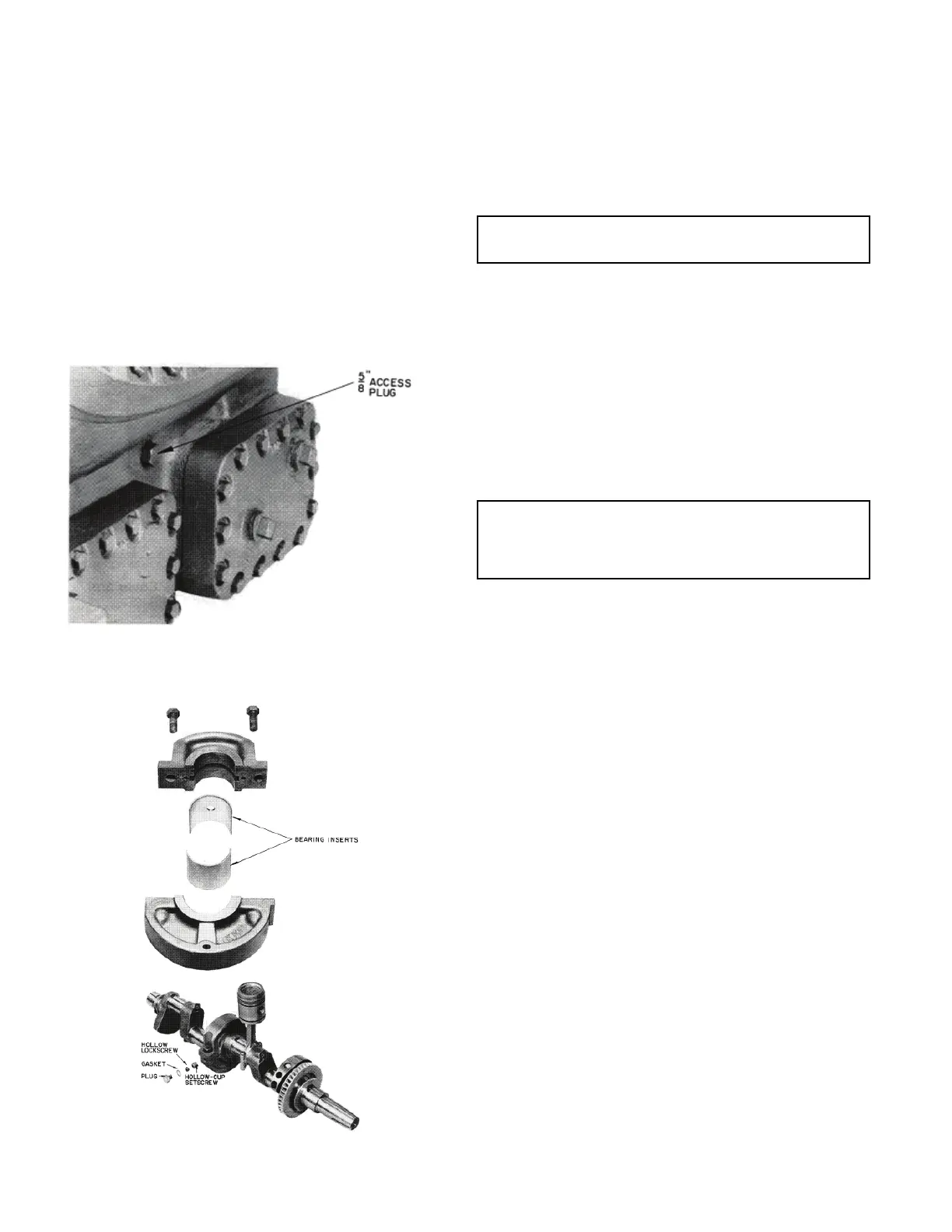
On 5H80-126 units, remove hollow-center main bearing lock
screw located beneath plug (see Fig. 23) and loosen hollow-cup
setscrew (see Fig. 24) until center main bearing can be slid from
its support. On 5H86, 120, and 126 units, disconnect oil line to
center main bearing. Remove crankshaft through pump-end open-
ing.
Normally it is not necessary to remove the oil separator impeller
(Refer to Fig. 11) from the 5H120 or 126 shaft. If impeller must be
removed for any reason, however, immerse it in hot water or oil
until heated to 180°F or more. Remove all traces of water before
reassembly. Do not heat impellers with torch.
Fig. 23 — 5H80-126 Center Main Bearing Housing
Setscrew Location
Fig. 24 — Center Main Bearing (5H120 and 126)
INSPECTION
Check crankshaft journals for wear and tolerances (refer to
Table 5). Remove crankshaft plugs, check oil passages and clean
if clogged.
Connecting-rod bearing inserts and main bearings are available for
crankshafts reground from 0.010 in., 0.020 in., or 0.030 in. under-
sized. Factory-reground crankshafts are stamped on both ends
with an A (0.010 in. undersized), B (0.020 in. undersized), or C
(0.030 in. undersized).
All instructions for field grinding apply only to standard stroke
crankshafts.
On crankshafts reground locally, hold throw to 1.001 in. for 5F
compressors and to 1.376 in. on 5H compressors. Stamp A or B on
crankshaft and pump-end bearing head next to oil pressure gauge
connection.
To determine maximum and minimum journal diameters for un-
dersized shafts, subtract the amount (in.) that the shaft will be
ground undersize from factory from the tolerances specified in
Table 5. For example, the factory tolerance for 5H40 seal-end
journal is 2.6225 in. to 2.6235 in. Tolerance for a crankshaft
reground to 0.010 in. undersize should therefore be held between
2.6125 in. and 2.6135 in.
REASSEMBLY
If 5H120 or 5H126 oil separator has been removed (see Step 2),
read impeller paragraph below before installing crankshaft.
When regrinding crankshaft, remove crankshaft plugs and clean
oil passages as well. Before replacing crankshaft, insert and tight-
en plugs, and reinstall the 5H120 and 126 oil separator impeller:
1. Insert dowel key (refer to Fig. 11) with axis parallel to axis of
crankshaft. Position key so chamfered edge is toward radius
of crankshaft journal.
2. Immerse oil separator impeller in oil or hot water to heat it to
180°F or more. If water is used, remove all traces before reas-
sembly. Install impeller on crankshaft with dowel key lined
up with impeller keyway. Impeller must fit key snugly.
3. Check that seal-end thrust washer is in place on dowel key in
crankcase.
Insert crankshaft and install pump-end bearing head, connecting
rod and piston assemblies, valve plate and cylinder heads. On
5H80-126 units, insert center main bearing setscrew and lock
screw. On 5H86, 120, and 126 units, reconnect oil line to center
main bearing.
Pump-End Main Bearing
DISASSEMBLY AND INSPECTION
On 5H40-86 units, remove pump-end cover. Remove pump-end
bearing head on all units. Inspect bearing for tolerances shown in
Table 5. If a pump-end main bearing is worn, remove bronze bear-
ing washer, and chisel out bearing. Inspect bearing housing for
wear (see Table 5) and damage. Remove any burrs. See Fig. 25.
IMPORTANT: Regrind crankshafts for 5H46, 66, 86, and 126
compressors in the field. Replace shafts with scored journals.
IMPORTANT: When regrinding the seal-end journal on 5H120
crankshaft, do not grind in the area of the oil separator impeller.
This is not journal area, and must remain intact or the oil separa-
tor impeller will not fit properly.
BE
A
RI
NG INSERTS
 Loading...