4
SERVICE
Service and repair of reciprocating compressors and other refriger-
ation components should be performed only by fully trained and
qualified personnel.
Lubrication System
OIL PUMPS
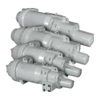
5F compressors. See Fig. 3 and 7.
5H40-86 compressors. See Fig. 3 and 8.
5H120,126 compressors, with automatically reversing oil pump.
Refer to Fig. 2 (A) and Table 3.
5H120,126 compressors, with manually reversing oil pump. Refer
to Fig. 2 (B), 4 and Table 3.
Service Notes
1. Compressor components are shown in normal order of
removal from compressor. See Fig. 5-8.
2. For replacement items, use Carlyle specified parts. See
Carlyle 5F, H Specified Parts list for compressor part inter-
changeability.
3. Before servicing compressor, pump down the refrigerant as
follows:
a. Start compressor, close suction service valve, and reduce
crankcase pressure to 2 psig. Bypass low pressurestat
with jumper.
b. Stop compressor; close discharge service valve to isolate
it from system.
c. Recover or reclaim any residual refrigerant. Drain oil if
necessary.
4. After disassembly, clean all parts with solvent. Use mineral
spirits, white gasoline or naphtha.
5. Before assembly, coat all parts with compressor oil and clean
and inspect all gasket surfaces. Replace all gaskets with new,
factory-made gaskets, and lightly coat with oil. See Table 4
for torque values.
6. After reassembly, evacuate compressor and open suction and
discharge valves. Restart compressor and adjust refrigerant
charge.
NOTE(S):
a. By itself, the automatic reversing oil pump cannot be installed in place of the
manually reversing oil pump or vice versa. The complete bearing head
assembly with the oil pump (auto or manual) is interchangeable as a complete
assembly.
MANUALLY REVERSING OIL PUMP
Oil Pump Inspection
Refer to Fig. 2, 7, 9 for 5F and 5H manually reversing oil pumps.
Also refer to 5H120, 126 section “AUTO REVERSING OIL
PUMP” on page 10.
Drain oil below level of pump-end bearing head. Remove bearing
head. Complete end-bell assembly must be removed to access
bearing head assembly with oil pump on 5H40-86 models. Check
oil pump rotor for end play. Maximum allowable movement of ro-
tor is 0.0025. If there is excessive end play, reposition oil pump
bushing in bearing head as described below.
Tum rotor. If there is more than a slight drag, remove pump cover
and disassemble oil pump checking all parts for wear and damage.
Inspect oil pump bushing for scoring. Replace bushing if scored. If
bearing head is scored, replace complete bearing head and oil
pump assembly.
Oil Pump Bushing Installation
See Fig. 3 and 4. Position the bushing oil groove at top (running
from 12:00 to 6:00) when the bearing head is installed. Press new
bushing into the pump-end bearing head from the inner side of the
head with the chamfered end entering first.
Oil Pump Bushing Position
1.
a. 5F20-60 and 5H40-86: Place 0.001 in. circular field
fabricated shim against bushing and install pump. Shim
between bushing and oil pump rotor. Complete assembly
of oil pump with gasket and cover. See Fig. 3.
b. 5H120, 126: Place 0.015 in. (1/64 in.) shim between port
insert and oil pump cover. Complete assembly of oil
pump and pump cover without using pump cover gasket.
See typical arrangement shown Fig. 4.
2. Tap bushing with suitable cylindrical positioning tool to seat
it against shim. See typical arrangement shown in Fig. 3.
a. 5F20-60 and 5H40-86: Disassemble oil pump and
remove shim. Reassemble oil pump. Check for binding.
(See Fig. 3.)
b. 5H120, 126: Remove oil pump cover and shim. Reas-
semble pump cover with gasket. Check for binding.
3. Install bearing head on compressor. Line up tang on oil pump
rotor shaft with slot in end of crankshaft. Check oil pump for
proper direction of rotation.
4. Refill compressor oil to proper level. Observe oil pressure
when starting compressor. Correct oil pressure should be
45 to 55 psig above suction pressure.
Table 3 — 5H120 and 126 Compressor Oil Pump
History Reference
TYPE
a
FIG.
DATE
MANUFACTURED
SERIAL NO. BREAK
Auto-
Reversing
2
1960-1968 and Starting
March 1986
From 0447119 to
A901765 and Starting
1086J01967
Manually
Reversing
2
Starting 1969 and
Ending March 1986
Starting A901765 and
Ending 1086J---
WARNING
Oil pump assembly must be flush with coverplate surface, but
must not protrude beyond bearing head surface.
w