3
If shaft seal housing temperature exceeds 170°F, STOP THE
COMPRESSOR. DO NOT restart until the cause of overheating
has been identified, and the condition corrected.
OIL COOLER USAGE
The accessory oil cooler maintains safe operating oil tempera-
tures when:
1. Applying long stroke compressors (5H46, 66, 86 and 126).
For added reliability, an oil cooler is recommended on all
long stroke models regardless of operating range or type of
refrigerant. Additional heat of friction from extended piston
travel on long stroke models increases oil temperatures.
2. The suction gas becomes highly superheated.
a. The compression ratio exceeds 5:1 on R-22 systems.
b. Application data indicates the need for an oil cooler for
R-134a systems. The compression ratio can be deter-
mined from the following formula:
NOTE: Do not operate unloaders at saturated suction tempera-
tures at or below 0°F without prior approval from Carlyle
Engineering.
3. The compressor operates fully unloaded for prolonged peri-
ods. Under these conditions, suction gas levels may not suf-
fice to remove the heat of compression and friction. This
condition can occur in any application, but is most likely in
low-temperature systems or variable volume applications
that use hot-gas bypass to maintain specified conditions
under low evaporator load. Refer to 5F, H Application Data
for additional information.
Adjust water flow rate through oil cooler to maintain 100°F to
120°F oil temperature returning to compressor. Crankcase tem-
perature must remain below 140°F; shaft seal temperature at the
seal housing should not exceed 170°F.
Tables 1 and 2 list maximum working pressures for oil and water
and estimated water flow rates for various oil cooler/compressor
combinations. For additional information, see Accessory Oil
Cooler Installation Instructions.
NOTE(S):
a. Flow rate based on 80°F entering water.
Check Water-Cooled Heads
To prevent oil breakdown and sludge formation, the discharge
gas temperature must remain below 275°F. Water-cooled
cylinder heads are available as an accessory for this purpose. See
Accessory Water-Cooled Head Package Installation Instructions
for additional information.
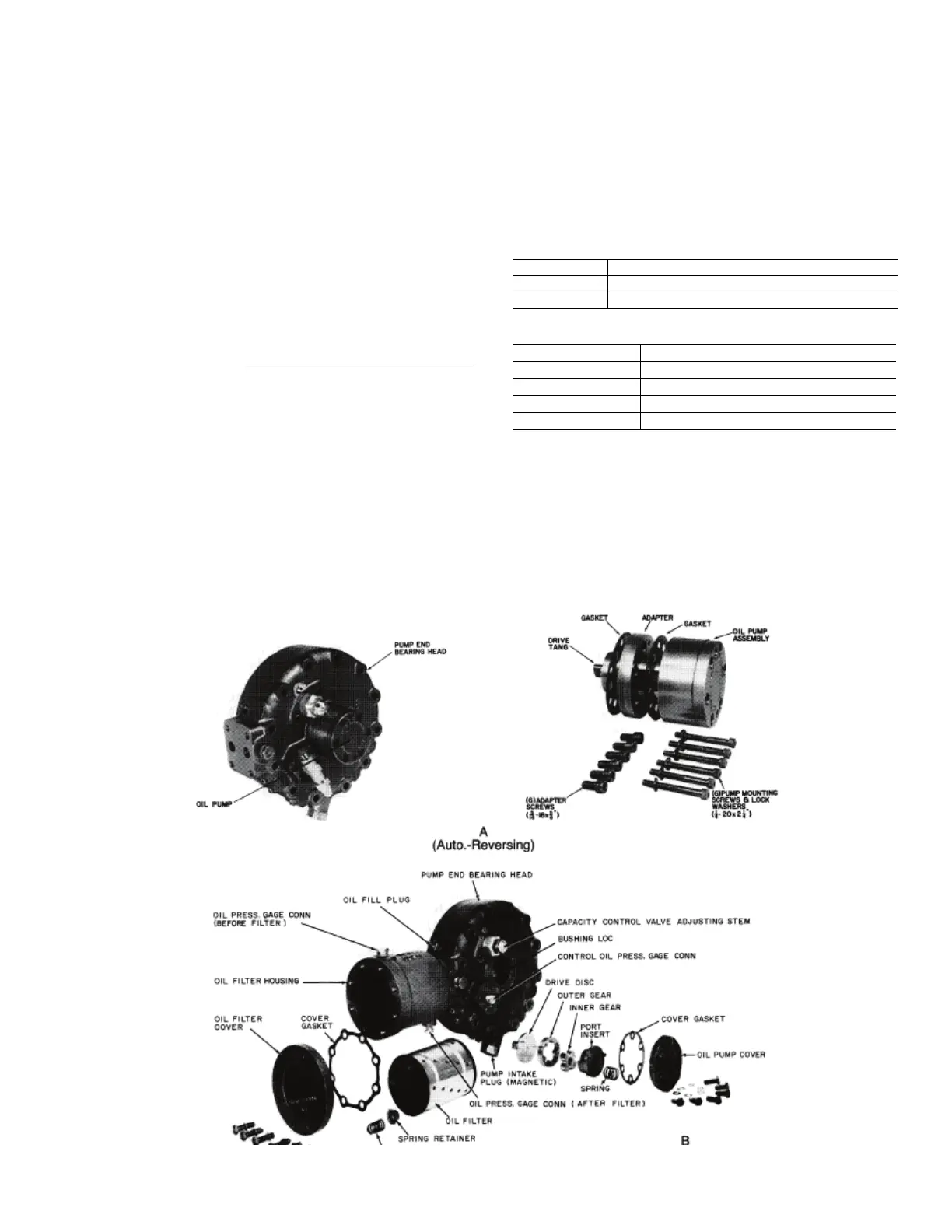
Fig. 2 — Oil Pump and Filter Assembly (5H120, 126)
Compression Ratio = Absolute Discharge Pressure
Absolute Suction Pressure
Table 1 — Oil Cooler Maximum Working Pressure
TYPE PRESSURE
OIL 250 psig
WATER 150 psig
Table 2 — Oil Cooler Estimated Water Flow Rates
COMPRESSOR GPM
a
5F 1/4-1
5H4Q-66 1-2
5H80,86 11/2-3
5H120,126 2-4
01
L
PR($$
,
GAGE
OON
~FO
R!;;
IL £R )
01
FILTEfl:
COVE
lR
PIN'
llNO
OC.,.
RlNS
ffE.W
A
(
Au
,
to.-Reverslng)
ij
H
~AD
OO
N
'tllO
L OIL
PRE
SS,
~E
C-QN:N
DI
SC
UR
GfAR
INIJll
~R
G'~AI!
.. ot::
·-·
11£SS
,
~E
CO:NN
( A
HE
R
Fl
Lnfl:
l
••
.,.
01
L , 1
Ll
i
!!:I!
SPR
ING
11£
TAI £R 8