To Read Refrigerant Pressures
during pumpout or leak testing:
1.
The LID display on the machine control center is suitable for determining refrigerant-side
pressures and low (soft) vacuum. For evacuation or dehydration measurement, use a
quality vacuum indicator or manometer to ensure the desired range and accuracy. This can
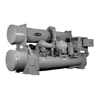
be placed on the Schrader connections on each vessel (Figure 7 and Figure 8) by removing
the pressure transducer.
2.
To determine utility vessel pressure, a 30 in.-0-400 psi (-101-0-2760 kPa) gage is attached
to the vessel.
3.
Refer to Figure 32 for valve locations and numbers.
CAUTION
CAUTION
!
Transfer, addition, or removal of refrigerant in spring-isolated machines may
place severe stress on external piping if springs have not been blocked in both
up and down directions.
Click here for Figure 32 — Pumpout Arrangement and Valve Number Locations
(12-ft Vessel Shown)

 Loading...