Contents
List of Figures
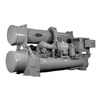
Figure 1 — 17/19EX Identification
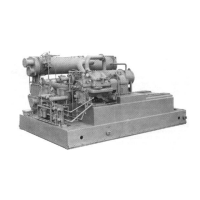
Figure 2 — Typical 17EX Installation
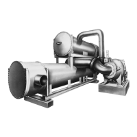
Figure 3 — Typical 19EX Installation
Figure 4 — Refrigerant, Motor Cooling, and Oil Cooling Cycles
Figure 5 — Hermetic Compressor Lubrication System (EX Compres-
sor Shown)
Figure 6 — Open-Drive (17 Series) Lubrication Cycle
Figure 7 — 17EX Controls and Sensor Locations
Figure 8 — 19EX Controls and Sensor Locations
Figure 9 — Control Center (Front View); Shown with Options Module
Figure 10 — Control Sensors (Temperature)
Figure 11 — Control Sensors (Pressure Transducer, Typical)
Figure 12 — Power Panel without Options (Open-Drive Machine
Shown)

 Loading...