Unit-Mounted Wye-Delta Starter (Optional)
—
The 19XR chiller may be equipped with a wye-delta starter
mounted on the unit. This starter is intended for use with
low-voltage motors (under 600 v). It reduces the starting
current inrush by connecting each phase of the motor
windings into a wye configuration. This occurs during the
starting period when the motor is accelerating up to speed.
Once the motor is up to speed, the starter automatically con-
nects the phase windings into a delta configuration. Starter
control, monitoring, and motor protection is provided by
Carrier’s Integrated Starter Module (ISM).
CONTROLS
Definitions
ANALOG SIGNAL — An analog signal varies in propor-
tion to the monitored source. It quantifies values between
operating limits. (Example: A temperature sensor is an ana-
log device because its resistance changes in proportion to
the temperature, generating many values.)
DISCRETE SIGNAL — A discrete signal is a 2-position rep-
resentation of the value of a monitored source. (Example: A
switch produces a discrete signal indicating whether a value
is above or below a set point or boundary by generating an
on/off, high/low, or open/closed signal.)
General — The 19XR hermetic centrifugal liquid chiller
contains a microprocessor-based control center that moni-
tors and controls all operations of the chiller (see Fig. 7).
The microprocessor control system matches the cooling
capacity of the chiller to the cooling load while providing
state-of-the-art chiller protection. The system controls cool-
ing load within the set point plus the deadband by sensing
the leaving chilled water or brine temperature and regula-
ting the inlet guide vane via a mechanically-linked actuator
motor. The guide vane is a variable flow pre-whirl assem-
bly that controls the refrigeration effect in the cooler by
regulating the amount of refrigerant vapor flow into the com-
pressor. An increase in guide vane opening increases capac-
ity. Adecrease in guide vane opening decreases capacity. The
microprocessor-based control center protects the chiller by
monitoring the digital and analog inputs and executing
capacity overrides or safety shutdowns, if required.
PIC II System Components — The chiller control
system is called the PIC II (Product Integrated Control II).
See Table 1. The PIC II controls the operation of the chiller
by monitoring all operating conditions. The PIC II can di-
agnose a problem and let the operator know what the prob-
lem is and what to check. It promptly positions the guide
vanes to maintain leaving chilled water temperature. It can
interface with auxiliary equipment such as pumps and cool-
ing tower fans to turn them on when required. It continually
checks all safeties to prevent any unsafe operating condi-
tion. It also regulates the oil heater while the compressor is
off and regulates the hot gas bypass valve, if installed. The
PIC II controls provide critical protection for the compres-
sor motor and controls the motor starter.
5
1
2
3
4
6
LEGEND
1—Ready-Start Micro Input/Output Card
2—Circuit Breaker 2 (CB2):
Machine Control and Heater Power
3—Circuit Breaker 3 (CB3): Oil Pump Power
4—Ready-Start Micro Central Processing Unit Card (CPU)
5—Restart Micro Power Card (hidden, not depicted)
6—Restart Micro Bypass Card (hidden, not depicted)
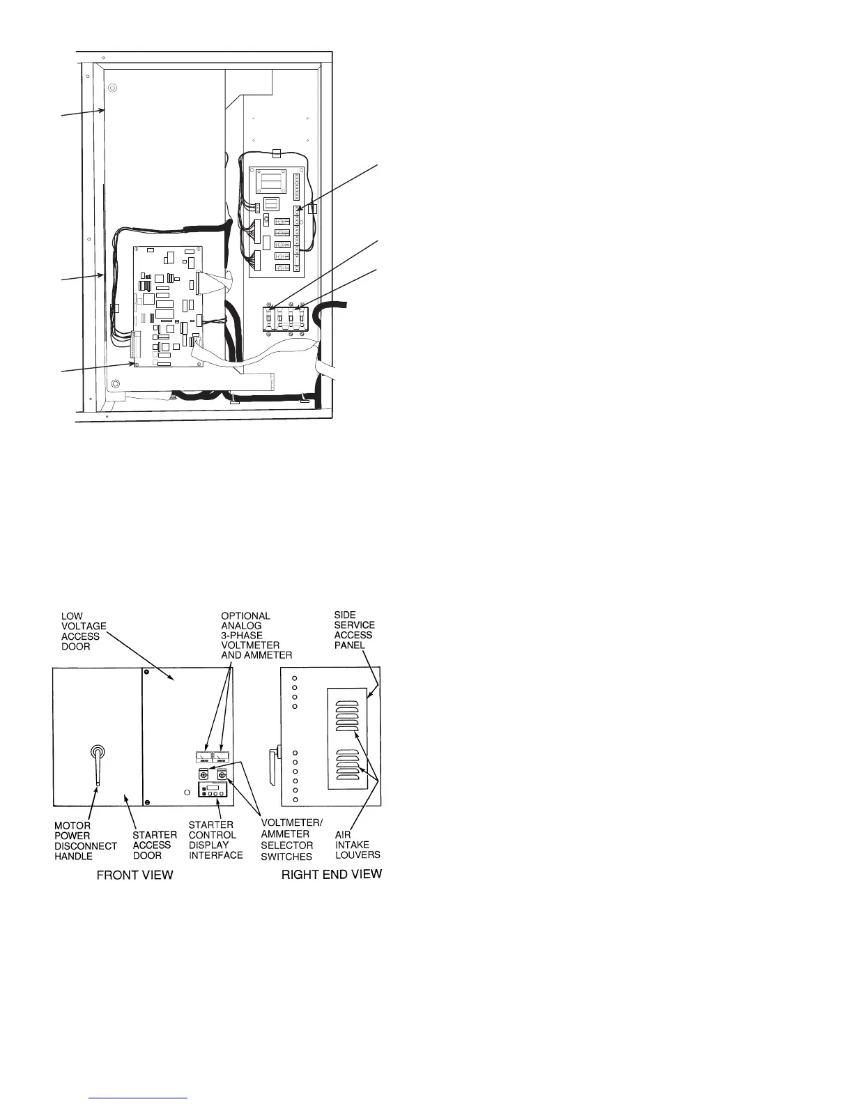
Fig. 5 — Solid-State Starter Box,
Internal View
Fig.6—Typical Starter External View
(Solid-State Starter Shown)
10

 Loading...


