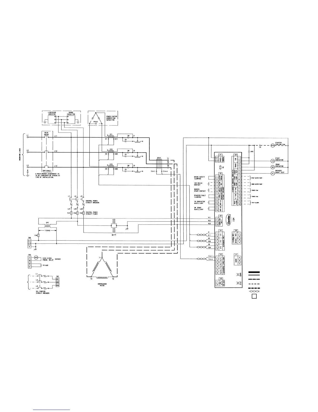
Fig. 47 — Typical Primary Reactor Starter Wiring Schematic (Medium Voltage)
LEGEND
AUX — Auxiliary
C—Contactor
CB — Circuit Breaker
COMM — Communication
COND — Condenser
CPT — Control Power Transformer
CR — Control Relay
CT — Current Transformer
DS — Disconnect Switch
EVAP — Evaporator
FU — Fuse
G—Ground
GFCT — Ground Fault Current Transformer
HPR — Horsepower
ISM — Intergrated Starter Module
L—Main Power Supply
LL — Control Power Supply
LVG — Leaving
M—Contactor
MTR — Motor
PRESS — Pressure
PT — Power Transformer
ST — Shunt Trip
STAT — Status
TB — Terminal Block
TRANS — Transition
VFD — Variable Frequency Drive
VL — Wire Label
Starter Vendor Power Wiring
Starter Vendor Control Wiring
Field Installed Power Wiring
(supplied by others)
Field Installed Control Wiring
(supplied by others)
Option — Starter Vendor Wiring
Twisted Pair Wiring by Starter Vendor
Customer Terminal Connection
99

 Loading...


