19
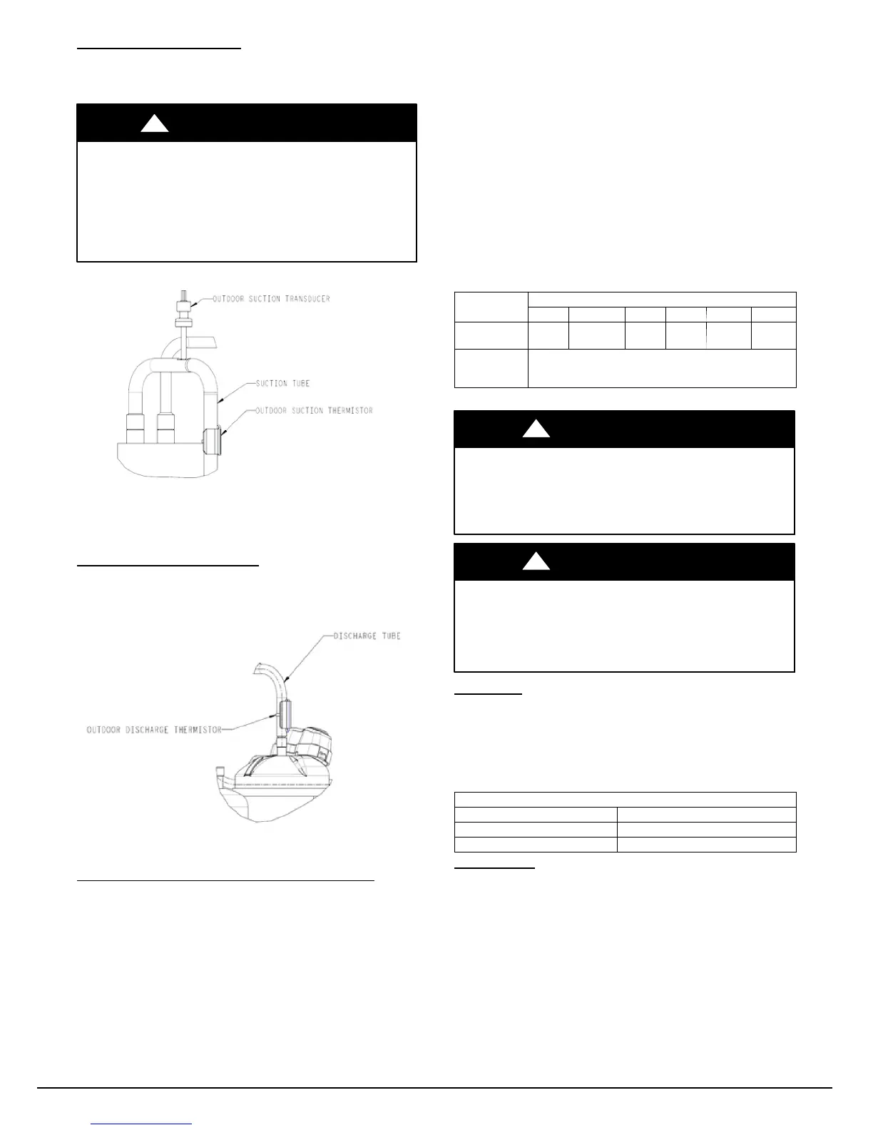
Suction Thermistor (OST)
Suction Thermistor is used for assisting in EXV control and must
be secured on the suction tube and aligned longitudinally to the
vertical surface of the tube axis (see Fig. 40).
CAUTION
!
UNIT DAMAGE HAZARD
Failure to follow this caution may result in equipment
damage or improper operation.
In order to minimize the ambient influence, make sure the
thermistor curved surface hugs the pipe surface and is
secured tight using the wire tie fished through the original
slot insulating polymer body.
A14023
Fig. 40 -- Suction Thermistor (OST) Attachment
(On Suction Tube)
Discharge Thermistor (ODT)
Discharge Thermistor is used for protection against over
temperature of the compressor. The ODT is located on the
compressor discharge stub-- out (see Fig. 41).
A14024
Fig. 41 - Discharge Thermistor (ODT)
Variable Speed Compressor Winding Resistance
This compressor operates with 3 --phase variable frequency PWM
variable voltage. For troubleshooting certain fault codes related to
compressor resistances, follow these steps:
1. Disconnect compressor power leads from the inverter MOC
terminals, U (YEL), V (RED), and W (BLK).
2. Measure the resistance between YEL to RED, YEL to BLK,
and RED to BLK and compare to Table 6 values. Each
resistance set should be equal.
3. Measure the resistance to ground for each lead.
4. If the resistances check out, reconnect power leads to
appropriate terminal.
5. If the resistances appear to be abnormal, it will be necessary
to measure the resistance at the compressor fusite terminals.
6. During the removal of the compressor fusite cap, do not re-
move the RTV sealant. Remove the harness plug, measure
the resistances, and compare to Table 6.
7. Special care will need to be taken with the replacement of
the compressor fusite cap. Make sure the two holes in the
compressor fusite terminal box are still full of RTV sealant
before the cap is reinstalled. The factory RTV can be reused
as long as none of it has been removed during the cap
removal.
8. Reinstall compressor sound blanket making sure discharge
thermistor and compressor power harness are routed as they
were from the factory
Table 6 – Variable Speed Compressor Resistance
(winding resistance at 70_F 20_F)
WINDING
MODEL 25VNA8
24A* 13, 24B* 25 36 37, 48 60
Between
terminals
.59
OHM
1.13
OHM
.59
OHM
.59
OHM
.37
OHM
.24
OHM
Between
terminal &
ground
>1 mega OHM
* 24A unit heigh t is 38 ---7/16” and 24B unit h eight is 31 ---5/8”
UNIT DAMAGE HAZARD
Failure to follow this caution may result in equipment damage
and/or improper operation.
Do not use Meggar for measuring the winding resistance.
CAUTION
!
UNIT DAMAGE HAZARD
Failure to follow this caution may result in equipment damage
and/or improper operation.
To maintain water integrity of the compressor fusite terminal
box, the two holes in outer ring need to be full of RTV sealant.
CAUTION
!
Fan Motor
If verification of proper operation is required for the fan motor
used in this unit, follow these steps:
1. Disconnect fan motor connector from control board.
2. Measure resistance between any 2 of the 3 leads present.
3. Compare measurement to values below
Fan Motor Resistance
Unit Size Resistance (Ohms)
13, 24B 21.2
24A, 25, 36, 37, 48, 60 11.1
Status Codes
Table 7 shows the status codes flashed by the amber status light.
Most system problems can be diagnosed by reading the status code
as flashed by the amber status light on the control board.
The codes are flashed by a series of short and long flashes of the
status light. The short flashes indicate the first digit in the status
code, followed by long flashes indicating the second digit of the
error code.
The short flash is 0.25 seconds ON and the long flash is 1.0 second
ON. Time between flashes is 0.25 seconds. Time between short
flash and first long flash is 1.0 second. Time between code
repeating is 2.5 seconds with LED OFF.
Codes are easily read from user interface (UI)
Manufacturer reserves the right to change, at any time, specifications and designs without notice and without obligations .
Catalog No: 25
N
8 --- 5 S I
Replaces: 25VNA8---4SI
 Loading...