4
Step 3 — Clearance Requirements
When installing, allow sufficient space for airflow clearance,
wiring, refrigerant piping, and service. Allow 24 in. (609.6 mm)
clearance to service end of unit and 48 in. (1219.2 mm) (above
unit. For proper airflow, a 6-- in. (152.4 mm) clearance on 1 side of
unit and 12 --in. (304.8 mm) on all remaining sides must be
maintained. Maintain a distance of 24 in. (609.6 mm) between
units. Position so water, snow, or ice from roof or eaves cannot fall
directly on unit.
On rooftop applications, locate unit at least 6 in. (152.4 mm) above
roof surface.
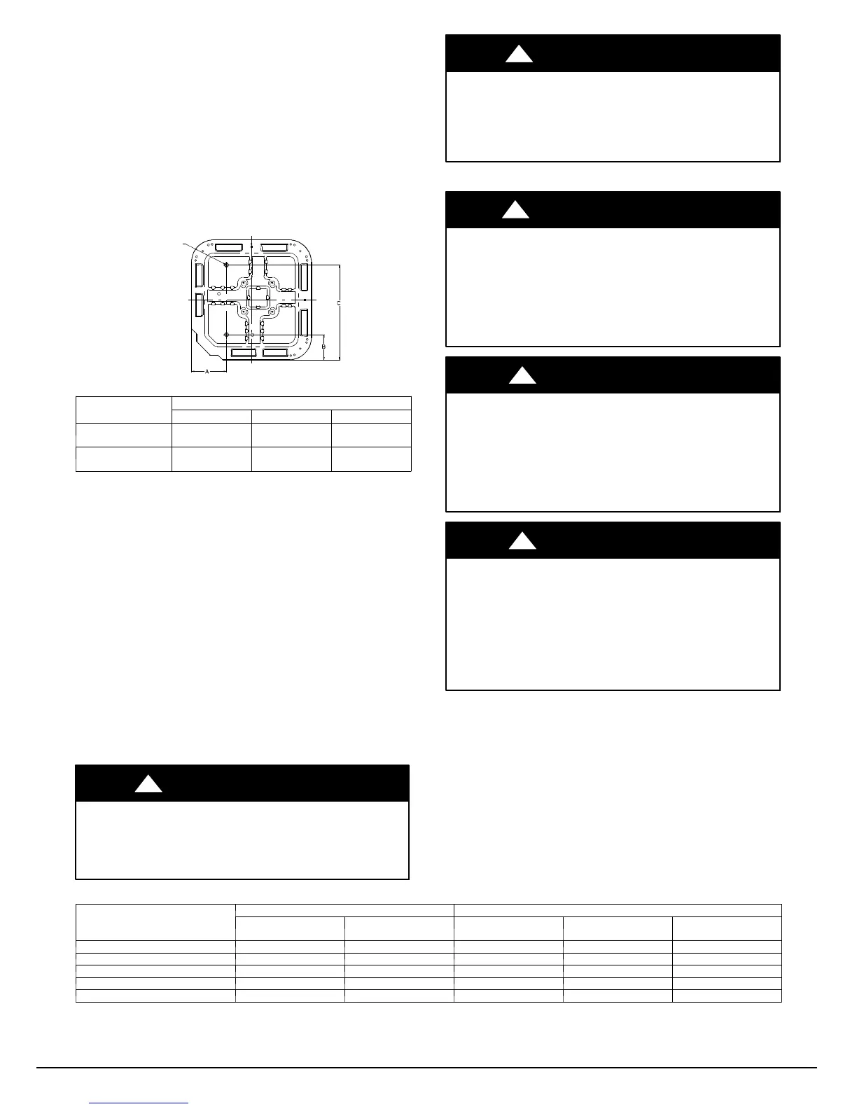
3/8--- in. (9.53 mm) Dia.
Tie---down Knockouts in
Basepan(2) Places
View From Top
A05177
UNIT BASE PAN
Dimension in. (mm)
TIEDOWN KNOCKOUT LOCATIONS in. (mm)
A B C
23 X 23
(596 X 596)
7---13/16 (198) 4---7/16 (102) 18---1/8 (458)
31.2 X 31.2
(792 X 792)
9---1/8 (232) 6---9/16 (167) 24---11/16 (627)
Fig. 3 -- Tie--down Knockout Locations
Step 4 — Operating Ambient
The minimum outdoor operating ambient in cooling mode is 40_F
(4.4_C) with Infinity Touch Control, 55_F (12.8_C) with
non--communicating systems. The maximum outdoor operating
ambient in cooling mode is 115_F (46.1_C). Compressor
protections will prevent cooling mode operation below minimum
ambient temperature range. The system may operate in cooling up
to 125_F(52_C) (52C) with significant reduced capacity cutback
above 115_F (46.1_C). Refer to Product Data “Detailed Cooling
Capacity” table. Low ambient cooling operation is not currently
available. The maximum heating operation ambient is 66_F
(18.9_C). Compressor protections will prevent starting below 10_F
(--12.2_C) and operation below 2_F ( -- 16.7_C).
Step 5 — Elevate Unit
Elevate unit per local climate and code requirements to provide
clearance above estimated snowfall level and ensure adequate
drainage of unit.
CAUTION
!
UNIT OPERATION HAZARD
Failure to follow this caution may result in equipment
damage or improper operation.
Do not allow water and/or ice to build up in base pan.
CAUTION
!
UNIT OPERATION HAZARD
Failure to follow this caution may result in equipment
damage or improper operation.
Locate the unit in such a way that it is stable in all
circumstances including adverse weather conditions.
Step 6 — Make Piping Connections
!
WARNING
PERSONAL INJURY AND UNIT DAMAGE
HAZARD
Failure to follow this warning could result in personal injury or
death.
Relieve pressure and recover all refrigerant before system
repair or final unit disposal. Use all service ports and open all
flow --control devices, including solenoid valves.
CAUTION
!
UNIT DAMAGE HAZARD
Failure to follow this caution may result in equipment
damage or improper operation.
Do not leave system open to atmosphere any longer than
minimum required for installation. POE oil in compressor is
extremely susceptible to moisture absorption. Always keep
ends of tubing sealed during installation.
CAUTION
!
UNIT DAMAGE HAZARD
Failure to follow this caution may result in equipment
damage or improper operation.
If ANY refrigerant tubing is buried, provide a 6 in. (152.4
mm) vertical rise at service valve. Refrigerant tubing lengths
up to 36 in. (914.4 mm) may be buried without further
special consideration. Do not bury lines longer than 36 in.
(914.4 mm).
Outdoor units may be connected to indoor section using accessory
tubing package or field-- supplied refrigerant grade tubing of correct
size and condition. For tubing requirements between 80 -- 100 ft.
(24.38 -- 30.48 m), capacity and performance losses can occur.
Follow the pipe sizing recommendations in the 25VNA8 Product
data to manage these losses. This unit shall not be installed with
greater than 100 ft (30.48 m) of equivalent line length.
Refer to Table 1 for field tubing diameters. No additional
accessories are required for line lengths between 80 -- 100 ft. (24.4
-- 30.5 m) on this product.
Table 1 – Refrigerant Connections and Recommended Liquid and Vapor Tube Diameters (in.)
UNIT SIZE
LIQUID VAPOR
†
Connection
Diameter
Tube
Diameter
Connection
Diameter
Max (Rated)
Diameter
Minimum
Tube Diameter
13, 24B* 3/8 3/8 3/4 3/4 5/8
24A*, 25 3/8 3/8 3/4 7/8 5/8
36, 37 3/8 3/8 3/4 7/8 5/8
48 3/8 3/8 7/8 (1---1/8) 3/4
60 3/8 3/8 7/8 (1---1/8) 3/4
* *24A unit height is 38--- 7/16”, 24B unit height is 31--- 5/8
{ Units are rated with 25 ft. (7.6 m) of lineset. See Product Data sheet for performance data when using different size and length line sets.
Notes:
1. Do not apply capillary tube indoor coils to these units.
Manufacturer reserves the right to change, at any time, specifications and designs without notice and without obligations .
Catalog No: 25
N
8 --- 5 S I
Replaces: 25VNA8---4SI
 Loading...