OPERATION
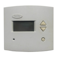
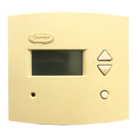
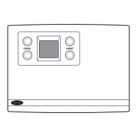
Hold, Fan, and Mode Button Operation —
Press-
ing the Hold button disables the time and temperature sched-
ule and holds the current desired temperature set point. When
a Hold is active, the HOLD annunciator is displayed on the
thermostat screen. To release the Hold, press the Hold but-
ton a second time.
The Fan button selects fan operation. When the fan is set
to ON, the fan will run continuously. When the fan is set to
AUTO, the fan will run during heating and cooling opera-
tion only.
The Mode button selects the operating mode of the ther-
mostat. If OFF is selected, the thermostat will not enter Heat-
ing or Cooling mode. If HEAT is selected, the thermostat
will only enter Heating mode (if the room temperature is
below the heating set point). If COOL is selected, the ther-
mostat will only enter Cooling mode (if the room tempera-
ture is above the cooling set point). If AUTO is selected, the
thermostat will enter Heating or Cooling mode based on the
room temperature and the heating and cooling set points. Heat
pumps also have an EHEAT selection. If EHEAT is selected,
the heat pump will use the second stage of heating to pro-
vide heat. The annuciator for each selection will be dis-
played on the thermostat when selected.
Thermostat Output Assignments — The thermo-
stat output assignments, based on configuration, are shown
in Table 3.
Five-Minute Compressor Short-Cycle Protec-
tion —
The timer prevents the compressor from starting
until it has been off for at least 5 minutes. The 5-minute timer
can be disabled (for one cycle only) by simultaneously press-
ing the Fan button and the Up button.
Fifteen-Minute Staging Timer — When multi-stage
heating or cooling is used, the staging timer prevents any
higher stage from energizing until at least 15 minutes has
passed from the start of the previous stage. The timer is dis-
abled if the temperature demand is greater than 5 degrees.
Two-Minute Minimum On Time — In normal op-
eration, when a stage is energized, it must remain on for at
least 2 minutes.
Heating/Cooling Set Point Minimum Differ-
ence —
A minimum difference of 3 degrees is enforced
between the heating and cooling set points. The thermostat
will not allow the set points to be set within 3 degrees of
each other.
Auto-Changeover Timer — When the auto-changeover
mode is selected, the thermostat will not change from heat-
ing to cooling or cooling to heating until an opposite de-
mand has existed for a minimum of 10 minutes. The timer
is disabled if the heating or cooling set point is changed.
Power-On Thermostat Check — When power is ap-
plied to the thermostat, all possible display annunciators are
turned on for a few seconds. The thermostat then indicates
the current mode and configuration information with a 2-digit
code. The following codes can be displayed: AC - single-
speed air conditioner, HP - single-speed heat pump,A2 - two-
speed air conditioner, and H2 - two-speed heat pump.
Error Codes — The thermostat will display the follow-
ing error codes if errors are detected:
E1 — If the thermostat cannot properly read room tempera-
ture, the thermostat will display an E1 and all outputs (ex-
cept the fan if on), will be deenergized.
E2 — If the AC line voltage drops below the minimum level,
all outputs are deenergized and the thermostat will display
an E2. The E2 error will remain until proper line voltage has
been restored (plus 15 seconds). If the line voltage is com-
pletely interrupted, the thermostat display will immediately
go blank.
Table 3 — Thermostat Output Assignments
DIP SWITCH
CONFIGURATION
COOLING
STAGE 1
COOLING
STAGE 2
HEATING
STAGE 1
HEATING
STAGE 2
HEATING
STAGE 3
UNIT TYPE STAGES
AC 1 Y/Y2 N/A W/W1 O/W2 N/A
HP 1
Y/Y2
O/W2
N/A Y/Y2
EMERGENCY
HEAT
W/W1
N/A
AC 2 Y1 Y/Y2 W/W1 O/W2 N/A
HP 2
Y1
O/W2
Y/Y2 Y1 Y/Y2 W/W1
LEGEND
AC — Air Conditioner
DIP — Dual In-Line Package
HP — Heat Pump
N/A — Not Available
N/C — Normally Closed
N/O — Normally Open
NOTES:
1. Heating stage 3 is only for 2 stage heat pump applications.
2. All relays except where noted are N/O, dry contacts.
3. Relay B is N/C. Relay B opens when O/W2 closes. See Fig. 1 for
relay locations.
11
 Loading...


