FREE CONNECT APP AVAILABLE
at www.carrier.com/connectstat
Wi-Fi
®
is a registered trademark of Wi-Fi Alliance
®
Corporation.
Android is a registered trademark of Google Inc. / Apple is a registered
trademark of Apple Corporation
WIRING DIAGRAMS WIRING DIAGRAMS
997-015110-3-R 11-808-575-01
Quick Start Guide
Carrier
®
Connect
™
Wi-Fi
®
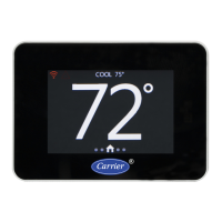
Commercial Thermostat
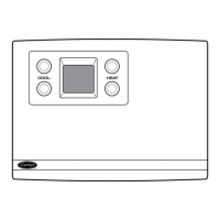
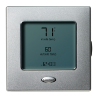
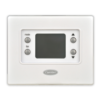
WHAT’S IN THE BOX
COMPATIBILITY CHECK
This Wi-Fi
®
thermostat is designed to work with 24V AC
systems requiring both R & C wires. This includes gas,
electric, oil, forced air, variable speed, heat pump and
radiant heat. It can be configured for:
› Heating: 1-4 stages (Y1, Y2, W1, W2)
› Cooling: 1-3 stages (Y1, Y2, *)
› Dehumidification: cooling only 1-3 stages (Y1, Y2, *)
or Carrier’s Humidi-MiZer™ adaptive dehumidification
system 1-2 stages (Y1, Y2, *)
› Heat pump: with auxiliary & emergency heat
(Y1, Y2, W1, W2, *)
› Fan Single Speed (G)
› Power (R, C)
› Dual fuel systems (heat pump with furnace)
› Outdoor Air Temperature (OAT) or Remote Sensor
(optional)
Quick Start
Guide
Security ScrewAnchors
and Screws
Thermostat Wall PlateThermostat Base
Remote Sensor
Pigtail
2-Stage Heat 2-Stage Cool
THERMOSTAT
*
W2
Y1
Y2
W1
G
R
C
Single Stage Air Handler
INDOOR
Y1
C
RR
C
G
W1
Y1
2-Stage Air Handler
INDOOR
Y1
Y2
G
C
RR
C
G
W1
W2
Y1
Y2
Single Stage HP
OUTDOOR
Y1
W1
G
R
C
1-Stage Heat 3-Stage Cool
THERMOSTAT
*
W2
Y1
Y2
W1
G
R
C
Y1
Y2
G
R
C
Y3
1-Stage Heat 2-Stage Cool
THERMOSTAT
*
W2
Y1
Y2
W1
G
R
C
Single Stage Air Handler
INDOOR
Y1
C
RR
C
G
W1
Y1
2-Stage Heat 2-Stage Cool
THERMOSTAT
*
W2
Y1
Y2
W1
G
R
C
2-Stage HP
OUTDOOR
Y1
Y2
W1
G
R
C
1-Stage Heat 1-Stage Cool
THERMOSTAT
*
W2
Y1
Y2
W1
G
R
C
2-Stage AC
OUTDOOR
1-Stage Heat 1-Stage Cool1
THERMOSTAT
*
W2
Y1
Y2
W1
G
R
C
2-Stage AC
OUTDOOR
Single Stage Air Handler
INDOOR
Y1
G
C
RR
C
G
W1
Y1
W1
W1 W1
W1
1-Stage Heat 2-Stage Cool
THERMOSTAT
*
W2
Y1
Y2
W1
G
R
C
1-Stage Heat 1-Stage Cool
THERMOSTAT
*
W2
Y1
Y2
W1
G
R
C
2-Stage Heat 2-Stage Cool
THERMOSTAT
*
W2
Y1
Y2
W1
G
R
C
Single Stage Air Handler
INDOOR
Y1
G
C
RR
C
G
W1
Y1
W1
24VAC
outputs
24VAC
outputs
24VAC
outputs
24VAC
outputs
24VAC
outputs
24VAC
outputs
24VAC
outputs
24VAC
outputs
24VAC
outputs
W1
W1
W2
AC or HP
AC or HP
AC or HP
AC or HP
1-Stage Heat 2-Stage Cool
THERMOSTAT
*
W2
Y1
Y2
W1
G
R
C
Y1
Y2
G
R
C
24VAC
outputs
AC w
ith Humidi-MiZer
®
Pink & Black Wire Only
(Tape off Pink Wire)
W2
W2
W2 W2
Y2Y2 Y2Y2
Y1
Y2
W1
G
R
C
W2
Y1
Y2
W1
G
R
C
W2
Y1
Y2
W1
G
R
C
W2
Y1
G
R
C
1-Stage Heat 1-Stage Cool
1-Stage Aux heat
THERMOSTAT
*
W2
Y1
Y2
W1
G
R
C
WATER SOURCE OR NON-CARRIER HEAT PUMP
AIR HANDLER OR DX FAN COIL / AC SPLIT SYSTEMAIR HANDLER OR DX FAN COIL / HEATPUMP SYSTEMPACKAGED ROOFTOP
24VAC
outputs
WSHP
O
Y1
G
R
C
2-Stage Heat 2-Stage Cool
2-Stage Aux heat
THERMOSTAT
*
W2
Y1
Y2
W1
G
R
C
24VAC
outputs
WSHP
O
AUX HEAT
W1
AUX HEAT
W1
Y2
W2
2-Stage Heat 2-Stage Cool
THERMOSTAT
*
W2
Y1
Y2
W1
G
R
C
Y1
G
R
C
Single Stage Air Handler
INDOOR
Y1
C
RR
C
G
W1
Y1
2-Stage Air Handler
INDOOR
Y1
Y2
G
C
RR
C
G
W1
W2
Y1
Y2
Single Stage HP
OUTDOOR
Y1
W1
G
R
C
1-Stage Heat 3-Stage Cool
THERMOSTAT
*
W2
Y1
Y2
W1
G
R
C
Y1
Y2
G
R
C
Y3
1-Stage Heat 2-Stage Cool
THERMOSTAT
*
W2
Y1
Y2
W1
G
R
C
Single Stage Air Handler
INDOOR
Y1
C
RR
C
G
W1
Y1
2-Stage Heat 2-Stage Cool
THERMOSTAT
*
W2
Y1
Y2
W1
G
R
C
Single Stage AC
OUTDOOR
Y1
Y2
G
R
C
2-Stage HP
OUTDOOR
Y1
Y2
W1
G
R
C
1-Stage Heat 1-Stage Cool
THERMOSTAT
*
W2
Y1
Y2
W1
G
R
C
2-Stage AC
OUTDOOR
1-Stage Heat 1-Stage Cool1
THERMOSTAT
*
W2
Y1
Y2
W1
G
R
C
2-Stage AC
OUTDOOR
Single Stage Air Handler
INDOOR
Y1
G
C
RR
C
G
W1
Y1
W1
W1 W1
W1
1-Stage Heat 2-Stage Cool
THERMOSTAT
*
W2
Y1
Y2
W1
G
R
C
1-Stage Heat 1-Stage Cool
THERMOSTAT
*
W2
Y1
Y2
W1
G
R
C
2-Stage Heat 2-Stage Cool
THERMOSTAT
*
W2
Y1
Y2
W1
G
R
C
Y1
Y2
G
R
C
Single Stage Air Handler
INDOOR
Y1
G
C
RR
C
G
W1
Y1
W1
24VAC
outputs
24VAC
outputs
24VAC
outputs
24VAC
outputs
24VAC
outputs
24VAC
outputs
24VAC
outputs
W1
W1
W2
AC or HP
AC or HP
AC or HP
AC or HP
1-Stage Heat 2-Stage Cool
THERMOSTAT
*
W2
Y1
Y2
W1
G
R
C
Y1
Y2
G
R
C
24VAC
outputs
AC w
ith Humidi-MiZer
®
Pink & Black Wire Only
(Tape off Pink Wire)
Y2Y2
Y1
Y2
W1
G
R
C
W2
Y1
Y2
W1
G
R
C
W2
Y1
Y2
W1
G
R
C
W2
W1
Y1
G
R
C
1-Stage Heat 1-Stage Cool
1-Stage Aux heat
THERMOSTAT
*
W2
Y1
Y2
W1
G
R
C
WATER SOURCE OR NON-CARRIER HEAT PUMP
AIR HANDLER OR DX FAN COIL / AC SPLIT SYSTEMAIR HANDLER OR DX FAN COIL / HEATPUMP SYSTEMPACKAGED ROOFTOP
24VAC
outputs
WSHP
O
Y1
G
R
C
2-Stage Heat 2-Stage Cool
2-Stage Aux heat
THERMOSTAT
*
W2
Y1
Y2
W1
G
R
C
24VAC
outputs
WSHP
O
AUX HEAT
W1
AUX HEAT
W1
Y2
W2
1. TURN POWER OFF
Turn off 24 VAC power at the equipment circuit breaker
or at the system switch. Confirm that power is OFF.
2. INSTALL THERMOSTAT
Position the thermostat base against your wall, and
determine if the accessory wall plate is desired to cover
horizontal 2 x 4 electrical box if installed., if so install
accessory wall plate. Position the thermostat base
against your wall (or wall plate if used) and determine if
the new screw locations align with prior locations. If base
does not align with existing anchor holes, mark new screw
locations with a pencil.
Drywall: Drill 3/16” hole for the anchor
Plaster: Drill 7/32” hole for the anchor
Pull wires through opening in base and secure base
to the wall using provided screws.
Comfort Control for Your Building
Part #: 33CONNECTSTAT




 Loading...