Installation, Service and
Troubleshooting Instructions
CONTENTS
Page
GENERAL ...................................1
INSTALLATION .............................2-7
Bypass Controller Placement .................2
Mounting Bypass Damper Actuator to Duct ....2
Wiring Requirements .........................2
Wiring Connections ..........................2
Sensor Adjustment ...........................3
Pressure Sensors ............................3
Calibration Pressure Set Point and
Selection of System Pressure Set Point .....6
Zone Damper Control ........................7
BYPASS CONTROLLER STAND-ALONE
OPERATION ...............................8
BYPASS CONTROLLER CONFIGURATION .....8
Manual Configuration ........................8
Computer Configuration ......................8
BYPASS CONTROLLER DISPLAY ............8-10
Information Display .........................10
Bypass Controller Initialization Display .......10
Alternate Information Display ................10
Display Freeze ..............................10
COMMUNICATION .........................10,11
Communication Interface ....................10
Device Address .............................10
Device Bus Number .........................11
Device Access Security Level ................11
SENSORS .................................11,12
Bypass Damper Duct Temperature
Sensor ...................................11
Pressure Sensor ............................11
Zone Temperature Monitoring ................11
Zone Temperature Sensor ...................11
Remote Room Temperature Sensor ..........12
Indoor-Air Quality Sensor ...................12
BYPASS DAMPER MODULATION ...........13-14
Damper Interface ............................13
Bypass Damper Mode .......................13
Bypass Damper Modulation .................13
Changeover Cycle ..........................13
Counterclockwise Open Damper
Modulation ...............................14
ZD/RD Actuator .............................14
PS Error Damper Position ...................14
Fan On Delay ...............................14
Fan Off Delay ...............................14
DIAGNOSTICS ............................14-18
Error Code Display ..........................14
System Errors (SE) ..........................15
Storage Failure (SF) Errors ..................15
Page
Hardware Failure (HF) Errors ................16
Bypass Controller Reset .....................18
ALARM OPTIONS ...........................18
Equipment Priority ..........................18
Communication Failure Retry Time ...........18
Re-Alarm Time ..............................18
Alarm Routing Control ......................18
Alarm System Name ........................18
ALARM DESCRIPTION .....................18,19
Indoor-Air Quality Status Alarm ..............18
NETWORK ACCESSIBLE VARIABLES ........19
BYPASS CONTROLLER
TROUBLESHOOTING ....................19-21
General Operating Problems .................19
Bypass Controller Communication
Problems .................................21
INDEX ......................................22
GENERAL
This manual provides detailed explanations of the opera-
tion of the Carrier Comfort System bypass controller and
each configurable function. The configurable functions al-
low the operation of the bypass controller to be adjusted to
match specific user needs and system requirements.
The bypass controller is the pressure moderator of the VVT
system. The pressure moderation ability of the bypass con-
troller makes a zoning system with a constant volume HVAC
unit possible. The bypass controller maintains system static
pressure based on the used-configured set point. The bypass
controller regulates system static pressure by opening its damper
when it measures a pressure above the system set point and
closing its damper when it measures a system pressure be-
low the system set point. If the system static pressure is within
3% of the system set point, the damper will remain at its
present position.
The bypass controller will receive the system mode from
the monitor thermostat and will modulate its damper ac-
cording to user-configured settings, system mode, and sen-
sor information. Only one bypass controller should be used
per one monitor thermostat.
NOTE: The 33CSBC--00 bypass controller will only work
with 33CSPS--01 and 33CSPS--02 pressure sensors.
NOTE: The Comfort System (33CS) bypass controller is not
compatible with a VVT Generation II Enhanced or Pre-
Enhanced device. The Carrier 33CS VVT system will not
support Enhanced or Pre-Enhanced devices.
Book 1 4
Tab 11a 13a
PC 111 Catalog No. 809-246 Printed in U.S.A. Form VVT-3SI Pg 1 7-95 Replaces: New
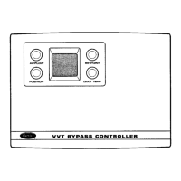
33CS
Variable Volume and Temperature (VVTT)
Bypass Controller
Manufacturer reserves the right to discontinue, or change at any time, specifications or designs without notice and without incurring obligations.