GB - 2
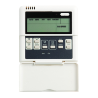
Type B Electronic Control
CONTROL TYPE "B"
Control
Functions
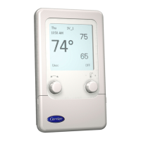
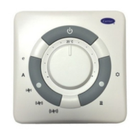
Control "B" have a knob to select the temperature, with a range
from 10°C to 30°C, and room temperature is maintained at the
selected value.
Fan operation
Use the speed selection button of the fan to select the manual or
automatic operating mode of the fan.
In manual mode, it is possible to select three fan speeds (low/medium/
high) according to the need, or the economy mode.
In the auto mode fan speed is regulated by a microprocessor in the
control in relation to the temperature chosen.
During installation, it is possible to select continuous fan operation
via the switch located on the electronic board (see section dip-
UYKVEJEQPſIWTCVKQP
In heating mode, the fan operation is delayed by approximately
one minute to allow the residual heat on the heat exchanger coil or
the electric heaters (if any) to be released.
Frost - protection
This function keeps the temperature from dropping below 7°C in rooms
not used for long periods of time. When this temperature is reached,
the control activates the valve and puts the fan on high speed.
The frost protection function can be activated through the
CUUQEKCVGFOKETQUYKVEJUGGUGEVKQPFKRUYKVEJEQPſIWTCVKQPKH
enabled, this function activates even when the control is in the OFF
position.
Type “B” control is used in 4-pipe systems and 2-pipe systems with
electric heater.
Assembly
Ŗ &QPQVRNCEGVJGEQPVTQNQPRCTVUQHYCNNUEQPVCKPKPIRKRGUQT
GNGEVTKEECDNGUDWVCVCDQWVEOHTQOVJGƀQQT
Ŗ &QPQVRNCEGVJGEQPVTQNPGCTJGCVUQWTEGUEWTTGPVUQHCKTFKTGEV
sunlight or in not well ventilated areas.
Ŗ 4GOQXGVJGNQEMKPIUETGYKPVJGWRRGTNGHVUKFGVQUGRCTCVGVJG
unit from the control (Fig. 2). Secure the unit on the wall and
mark the drill holes.
Ŗ &TKNNVJGJQNGURTGXKQWUN[OCTMGF
Avoid drilling with the plastic unit already placed on wall.
Ŗ 4GOQXGVJGEQPVTQNEQPPGEVQTUD[GZGTVKPIRTGUUWTGCUUJQYP
KPſI9KVJVJGEQPVTQNEQPPGEVQTUPQVKPRNCEGRTGRCTGVJG
electrical connections between this and the electric control box
RCPGNQHVJGHCPEQKNCUUJQYPKPVJGYKTKPIFKCITCOKPſI
(QTVJGURGEKſEEQPPGEVKQPDGVYGGPVJGEQPVTQNCPFVJGHCPEQKN
unit refer to the diagram shown on the unit.
Ŗ 6JGEQPPGEVKPIECDNGQHVJGHCPEQKNWPKVCPFVJGCEEGUUQT[ECDNGU
UJQWNFDGQHVJG*40(V[RGQTJKIJGTCEEQTFKPIVQ
'0UVCPFCTF
All electric connection cables should be at least 1,5 mm.
Ŗ %CTT[QWVVJGEQPPGEVKQPUVQVJGEQPVTQNEQPPGEVQTU(KI
Ŗ #HVGTEQPPGEVKQPUVQVJGEQPPGEVQTJCXGDGGPOCFGRNCEGKVKP
the corresponding housing on the unit.
Ŗ (KZVJGEQPVTQNVQVJGYCNNWUKPIVJGEQTTGURQPFKPIUETGYCPEJQTUQ.
Ŗ 2WVVJGEQPVTQNEQXGTDCEMVQKVURNCEGD[TGKPUVCNNKPIVJGUETGY
previously removed
(Fig. 2).
Fig. 3
Fig. 4
Fig. 2
P Screw
Q Screw anchor
P
QP
PQ
a
Z
]
X
^
Y
[
\
_
`
Fig. 5
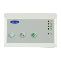
X 219'4DWVVQP
Y Blue LED - cooling operation
Z (#0DWVVQP
[ 4GF.'&JGCVKPIQRGTCVKQP
\ MODE button
] Green LED - energy saving operation
^ Temperature knob
_ Yellow LED - fan automatic speed selector
` 4GF.'&UHCPURGGFQRGTCVKQP
a Yellow LED - automatic heating/cooling operation
Wall-mounted control
1500
IMPORTANT:
$OOFRQQHFWLRQVEHWZHHQWKHXQLWDQGWKHFRQWUROPXVWEH
placed into a proper plastic conduit.
+DQGOHWKHFRQWUROZLWKH[WUHPHFDUH'RQRWWRXFKHOHFWURQLF
components to avoid damaging them.
'RQRWIRUJHWWRFRQÀJXUHWKHGLSVZLWFKHVLIVRUHTXLUHG
before closing the control.
7KHFRQWUROXQLWFRQQHFWLQJFDEOHVKRXOGEHD39&FDEOH
ZLWKPLQLPXPVHFWLRQRIPPòRUKLJKHU
8VHDFOLSWRMRLQWKHFRQWURORXWSXWFDEOHV)LJ
 Loading...