GB - 4
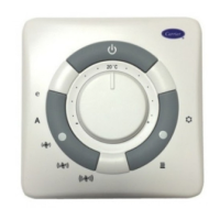
Type B Electronic Control
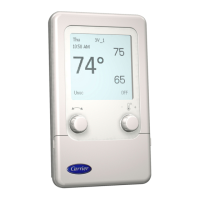
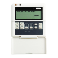
Control
Temperature selector
Its purpose is to maintain the temperature at the desired level. The
reference value at the centre of the range is 20°C.
By turning the knob towards the symbol ( – ) the temperature is
reduced from the original setting (minimum value is 10°C).
By turning the knob towards the symbol ( + ), the temperature is
raised from the original setting (maximum value is 30°C).
Energy saving button
This button activates the energ[UCXKPIHWPEVKQPYJKEJOQFKſGU
room temperature as follows: in heating, the selected temperature is
TGFWEGFD[u%KPEQQNKPIVJGUGNGEVGFVGORGTCVWTGKUTCKUGFD[u%
Light indicators
Blue LED
ON Indicates that the control is in cooling mode
Flashing Indicates that the control is in frost protection
mode (
).
5HG/('JURXSRQWKHULJKW
ON Indicates that the control is in heating mode (
).
Flashing Indicates the presence of a fault (sensor failed or
not connected)
<HOORZLED
JURXSRQWKHULJKW
ON Indicates that the control is in automatic mode (
).
Blue LED + <HOORZLED
Both ON Indicates that the control is in automatic mode
(
) - cooling mode .
Red LED<HOORZLED
Both ON Indicates that the control is in automatic mode
(
) - heating mode ( )
5HG/('VJURXSRQWKHOHIW
ON Indicates that the fan is operating at the selected
speed.
<HOORZ/('
JURXSRQWKHOHIW
ON Indicates that the selection of the fan speed is
set automatically.
Red / Blue LED
Flashing Indicates that the control is in
“Autotest”
mode
.
*UHHQ/('
ON Indicates that the control is in Energy Saving mode.
Flashing External contact is open.
'LSVZLWFKIXQFWLRQVPLFURVZLWFK
'LSVZLWFK
In open contact position, it allows to activate the frost protection
function
'LSVZLWFK
In open contact position, it permits the fan operation at the selected
URGGFGXGPKHVJGUGVRQKPVVGORGTCVWTGKUUCVKUſGF
'LSVZLWFK
In open contact position, it restricts the range of the temperature
selection knob according to the following limits:
Cooling: minimum selectable temperature: 23°C.
+HDWLQJ maximum selectable temperature: 21°C.
'LSVZLWFK
In open contact position, it permits to activate the fan periodically
GXGPKHVJGUGVRQKPVVGORGTCVWTGKUUCVKUſGFCKTUCORNKPI
'LSVZLWFK
In open contact position, it permits to activate the Booster Heating
function (additional heating).
'LSVZLWFKHVDQG
0QHWPEVKQPHQTVJKUOQFGN
NOTE:
)DFWRU\VHWWLQJLVZLWKDOOGLSVZLWFKHVLQFORVHSRVLWLRQ
8VHRIWHPSHUDWXUHVHQVRU
Internal sensor:
This is used in all installations where the control is wall-mounted. To
CEVKXCVGKVENQUGLWORGT,2CUUJQYPKPſIWTG#CPFQPVJGGNGEVTQPKE
board screenprint.
Remote sensor:
This is used on all installations with unitmounted control. It is
positioned on the return air, close to the fan. To activate it, close
LWORGT,2CUUJQYPKPſIWTG$CPFQPVJGGNGEVTQPKEDQCTF
screenprint.
127()DFWRU\VHWWLQJLVZLWKDFWLYDWHGLQWHUQDOVHQVRU
'LDJQRVWLFZDUQLQJV
The following alarm situations are indicated:
'HIHFWLYHVHQVRUVWKHUHG/('ÁDVKHV
Possible causes:
ŖHCKNWTGQTUJQTVEKTEWKVQHKPVGTPCNUGPUQT
ŖHCKNWTGQTUJQTVEKTEWKVQHYCVGTVGORGTCVWTGUGPUQT
Autotest
The autotest function is activated by holding the seasonal
changeover button pressed and at the same time pressing the “
” button three times within 1 second. In this way it is possible to
check the starting of all fan coils. The blue and red LEDs will begin
VQƀCUJ
Each of the various units will be activated for 10 seconds in the
following sequence:
Low fan speed.
Medium fan speed.
High fan speed.
&9 Motorized cold-water valve.
+9 Motorized hot-water valve.
X3 X3
Internal sensor 4GOQVGUGPUQT
Fig. A Fig. B
)LJ
)LJ
 Loading...