EasyManua.ls Logo

Carrier 38MBQ Series User Manual

Carrier 38MBQ Series
48 pages
To Next Page IconTo Next Page
Page #1 background imageLoading...
Page #1 background image
38MBQ
Outdoor Unit Single Zone Ductless System
Sizes 36 to 48
Service Manual
TABLE OF CONTENTS
PAGE
SAFETY CONSIDERATIONS 1.........................
INTRODUCTION 1...................................
MODEL/SERIAL NUMBER NOMENCLATURE 2..........
SPECIFICATIONS 3...................................
DIMENSIONS 4......................................
CLEARANCES 6.....................................
ELECTRICAL DATA 7................................
WIRING 7...........................................
CONNECTION DIAGRAM 7...........................
WIRING DIAGRAMS 8................................
FAN AND MOTOR SPECIFICATIONS 10.................
REFRIGERATION CYCLE DIAGRAMS 11................
REFRIGERANT LINES 12.............................
SYSTEM EVACUATION AND CHARGING 13.............
SYSTEM VACUUM AND CHARGE 13...................
ELECTRONIC FUNCTIONS 14.........................
TROUBLESHOOTING 16..............................
DIAGNOSIS GUIDES 17...............................
DIAGNOSIS AND SOLUTION 18.......................
DISASSEMBLY INSTRUCTIONS 36.....................
SAFETY CONSIDERATIONS
Installing, starting up, and servicing air−conditioning equipment
can be hazardous due to system pressures, electrical components,
and equipment location (roofs, elevated structures, etc.).
Only trained, qualified installers and service mechanics should
install, start−up, and service this equipment.
Untrained personnel can perform basic maintenance functions such
as cleaning coils. All other operations should be performed by
trained service personnel.
When working on the equipment, observe precautions in the literature
and on tags, stickers, and labels attached to the equipment.
Follow all safety codes. Wear safety glasses and work gloves. Keep
quenching cloth and fire extinguisher nearby when brazing. Use
care in handling, rigging, and setting bulky equipment.
Read this manual thoroughly and follow all warnings or cautions
included in literature and attached to the unit. Consult local building
codes and National Electrical Code (NEC) for special requirements.
Recognize safety information. This is the safety−alert symbol
!
!
.
When you see this symbol on the unit and in instructions or manuals,
be alert to the potential for personal injury. Understand these signal
words: DANGER, WARNING, and CAUTION.
These words are used with the safety−alert symbol. DANGER
identifies the most serious hazards which will result in severe personal
injury or death. WARNING signifies hazards which could result in
personal injury or death. CAUTION is used to identify unsafe
practices which may result in minor personal injury or product and
property damage. NOTE is used to highlight suggestions which will
result in enhanced installation, reliability, or operation.
!
WARNING
ELECTRICAL SHOCK HAZARD
Failure to follow this warning could result in personal
injury or death.
Before installing, modifying, or servicing system, main
electrical disconnect switch must be in the OFF
position. There may be more than 1 disconnect switch.
Lock out and tag switch with a suitable warning label.
EXPLOSION HAZARD
Failure to follow this warning could
result in death, serious personal injury,
and/or property damage.
Never use air or gases containing
oxygen for leak testing or operating
refrigerant compressors. Pressurized
mixtures of air or gases containing
oxygen can lead to an explosion.
!
WARNING
CAUTION
!
EQUIPMENT DAMAGE HAZARD
Failure to follow this caution may result in equipment
damage or improper operation.
Do not bury more than 36 in. (914 mm) of refrigerant pipe
in the ground. If any section of pipe is buried, there must be
a 6 in. (152 mm) vertical rise to the valve connections on
the outdoor units. If more than the recommended length is
buried, refrigerant may migrate to the cooler buried section
during extended periods of system shutdown. This causes
refrigerant slugging and could possibly damage the
compressor at start−up.
INTRODUCTION
This Service Manual provides the necessary information to service,
repair, and maintain the 38MBQ family of heat pumps. Section 2 of
this manual has an appendix with data required to perform
troubleshooting. Use the Table of Contents to locate a desired topic.
Question and Answer IconNeed help?

Do you have a question about the Carrier 38MBQ Series and is the answer not in the manual?

Carrier 38MBQ Series Specifications

General IconGeneral
BrandCarrier
Model38MBQ Series
CategoryAir Conditioner
LanguageEnglish

Summary

Important Safety Information

General Safety Precautions

Ensures proper installation and servicing by trained personnel, and emphasizes reading manuals and following codes.

Specific Hazard Warnings

Details Electrical Shock, Explosion, and Equipment Damage hazards and necessary precautions.

Service Manual Overview

Manual Purpose and Scope

Describes the manual's purpose to provide information for servicing, repair, and maintenance of the 38MBQ heat pumps.

Model and Serial Number Identification

Nomenclature Breakdown

Explains the meaning of each character in the model and serial number for identification.

Technical Specifications

Electrical, Piping, and Refrigerant Data

Details electrical ratings, piping lengths, connection sizes, refrigerant type, and charge amounts.

Outdoor Coil, Compressor, and Unit Dimensions

Provides specs for outdoor coil, compressor, unit dimensions, weight, and fan details.

Unit Dimensions and Diagrams

Outdoor Unit Configuration Overview

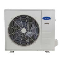
Illustrates the outdoor unit's physical layout with key dimensions and airflow paths.

36K Model Dimensions and Drawings

Provides detailed drawings and measurements for the 36K outdoor unit size.

Unit Dimensions and Diagrams (Cont.)

48K Model Dimensions and Drawings

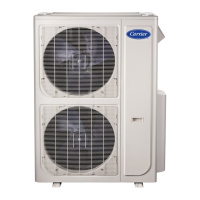
Presents detailed drawings and measurements for the 48K outdoor unit size.

Outdoor Unit Clearances

Required Installation Clearances

Specifies minimum clearance dimensions (A, B, C, D, E) around the outdoor unit for proper operation and maintenance.

Electrical Data and Wiring

Power Supply and Compressor Ratings

Details voltage, phase, MCA, MOCP, and compressor RLA for unit sizes.

Wiring Recommendations

Provides guidance on wire sizing, conductor types, and connection methods for power and communication.

Wiring Diagrams

36K Model Wiring Schematic

Presents the detailed wiring diagram for the 36K outdoor unit, showing component connections.

Outdoor Unit Main Board Connections

Lists and describes the function of each terminal (CN) on the outdoor unit's main board.

Wiring Diagrams (Cont.)

48K Model Wiring Schematic

Provides the detailed wiring diagram for the 48K outdoor unit, illustrating component interconnections.

Outdoor Unit Main Board Connections (48K)

Details the terminals and their functions on the outdoor unit's main board for the 48K model.

Fan and Motor Specifications

Outdoor Fan and Motor Details

Lists material, type, dimensions, model, phase, FLA, insulation class, and input/output for outdoor fans.

Refrigeration Cycle Diagram

Heat Exchange Process

Illustrates the refrigerant flow through indoor and outdoor heat exchangers, valves, and sensors.

Refrigerant Line Sizing and Installation

General Refrigerant Line Guidelines

Covers minimum/maximum lengths, insulation requirements, and installation precautions for refrigerant lines.

Piping and Refrigerant Charge

Details pipe sizes, refrigerant type (R410A), and charge amounts for different system sizes and lengths.

System Evacuation and Charging

Deep Vacuum Method

Explains the deep vacuum method using a pump and gauge to achieve 500 microns for system evacuation.

Triple Evacuation Method

Details the triple evacuation process involving vacuum, nitrogen purge, and pressure checks for a dry system.

System Operating Conditions

Outdoor Operating Range

Specifies the minimum and maximum outdoor DB temperatures for cooling and heating operation.

Electronic Functions and Protections

Compressor Protections

Describes protections like three-minute delay, top temperature, and discharge temperature protection.

Fan Speed Control and Inverter Protection

Details fan speed malfunctions and inverter module protection functions.

Defrosting Mode Operation

Defrosting Mode Conditions

Lists the conditions that trigger the defrosting mode based on temperature and running time.

Information Enquiry Function

Accessing Enquiry Status

Explains the procedure to enter the information enquiry status and navigate through displayed codes.

Troubleshooting Guide

Diagnostic Tools and Steps

Lists required tools and recommended steps for diagnosing unit problems, including checking diagnostic codes.

Indoor Unit Diagnostic Codes

Indoor Unit Error Code Reference

Details error codes (E0-E5, EC, EE) for indoor units, listing malfunctions and LED status indicators.

Outdoor Unit Diagnostic Codes

Outdoor Unit Error Code Reference

Lists error codes (E1, F0-F5, J0-J6) for outdoor units, specifying problems and their corresponding error codes.

EEPROM Parameter Error Diagnosis

Troubleshooting E0/F4 Error

Provides troubleshooting steps for EEPROM parameter errors (E0/F4), covering potential causes like installation mistakes or faulty PCBs.

Overload Current Protection Diagnosis

Troubleshooting F0 Error

Details the diagnosis and solution for overload current protection (F0), including checks for power supply and system blockage.

Communication Error Diagnosis

Troubleshooting E1 Error

Outlines diagnosis and solutions for E1 communication errors, focusing on wiring integrity and PCB functionality.

Electrical Component Testing

DC Voltage and Reactor Testing

Guides on testing DC voltage and reactor resistance to diagnose unit malfunctions and component integrity.

DC Fan Motor Diagnosis

Control Chip Voltage Checks

Explains how to measure DC motor voltage inputs and outputs at the control chip for troubleshooting.

Temperature Sensor Error Diagnosis

Troubleshooting Sensor Faults (E4/E5/F1-F3)

Provides steps to diagnose open or short circuits in temperature sensors, checking connections and resistance.

Refrigerant Leakage Diagnosis

Troubleshooting EC Error

Details the diagnosis and solution for refrigerant leakage detection (EC), including checking for leaks and blockages.

IPM Malfunction Diagnosis

Troubleshooting PO Error

Outlines troubleshooting for IPM/IGBT over-current protection (PO), including checks for wiring and component health.

Voltage Protection Diagnosis

Troubleshooting P1 Error

Details diagnosis and solution for over/under voltage protection (P1), including power supply and reactor checks.

Compressor Temperature Protection Diagnosis

Troubleshooting P2 Error

Provides steps to diagnose compressor top high temperature protection (P2), checking airflow and overload protector status.

Inverter Compressor Drive Error Diagnosis

Troubleshooting P4 Error

Outlines the diagnosis and solution for inverter compressor drive errors (P4), checking wiring, IPM, and compressor values.

Main Parts Checking Procedures

Temperature Sensor and Compressor Checks

Guides on checking temperature sensor resistance and compressor winding resistance for faults.

IPM Continuity Check

Details the procedure for measuring IPM resistance between specific terminals (P, UVWN, N) after discharging capacitors.

Disassembly Instructions - 36K Model

Removing Panel Plate

Details steps for removing the panel plate and fan assembly from the 36K outdoor unit.

Removing Electrical Components

Guides on disconnecting various electrical connectors and wires from the control board and components.

Removing Compressor and 4-way Valve

Provides steps to remove the compressor and four-way valve assembly, including refrigerant recovery.

Disassembly Instructions - 48K Model

Removing Fan Assembly and Panel Plate

Details steps for removing the fan assembly, grille, and panel components from the 48K outdoor unit.

Disconnecting Electrical Components (48K)

Guides on disconnecting fan motor connectors and wires from the IPM board and PCB.

Removing Compressor and Valves (48K)

Provides steps to remove the compressor, 4-way valve, and expansion valve, including refrigerant extraction.

Related product manuals