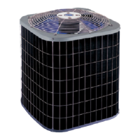
2
FEATURES AND BENEFITS (CONT.)
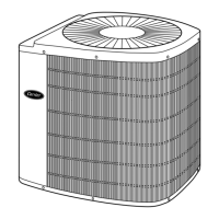
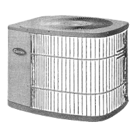
External Service Valves
Service valves are brass, front seating type. The 38YCC has sweat
field connections. Valves are externally located so refrigerant tube
connections can be made quickly and easily. Each valve has a
service port for ease of checking operating refrigerant pressures.
Easy Serviceability
One panel provides access to electrical controls. Removal of wire
dome gives access to fan motor and removal of the top gives access
to the coil and compressor. All models are equipped with a
compressor terminal plug.
Discharge Muffler
Minimizes low frequency sound and pressure pulsation generated
by compressor discharge gas.
Defrost Control Board
This board incorporates a built--in 5-- minute compressor
time--delay relay, defrost relay , defrost timer, and low--voltage
terminal board. The defrost control is a time/temperature initiation/
termination control which includes 4 field--selectable (DIP switch)
time periods of 30, 60, 90, and 120 minutes. This control also
includes a field selectable (DIP Switch) Quiet Shift defro st mode
which, if selected, maintains extremely quiet operation during
defrost.
PRODUCT NUMBER NOMENCLATURE
38YCC 018
7
10 SEER
Electric Heat Pump
Electrical Supply
7=230---1---50
9=400---3---50
Nominal Capacity
018 --- 1 --- 1 / 2 To n
024 --- 2 To n s
030 --- 2 --- 1 / 2 To n s
036 --- 3 To n s
042 --- 3 --- 1 / 2 To n s
048 --- 4 To n
060 --- 5 To n
3
Packaging
Series
A
REGISTERED
ISO 9001:2000
PHYSICAL DATA
UNIT SIZE 018---7A 024---7A 036---7A,9A 048---9A 060---9A
OPERATING WEIGHT (lb/kg) 130/59.0 140/63.5 215/97.5 226/102.5 259/117.5
COMPRESSOR TYPE Reciprocating Scroll
REFRIGERANT R --- 2 2
Control Piston
Charge (Lb/kg)
@15 Ft./4.6m
4.75 / 2.15 4.84 / 2.20 7.93 / 3.60 7.25 / 3.29 10.75 / 4.88
COND FAN Propeller Type, Direct Drive
Air Discharge Vertical
Air Qty (CFM/L/S) 2160 / 1020 2750 / 1300
Motor HP 1/10 1/4
Motor RPM 850 900
COND COIL Copper Tube, Aluminum Plate Fin
Face Area sq ft / sq m 9.1 / .84 12.4 / 1.15 22.4 / 2.08 18.7 / 1.74 22.4 / 2.08
Fins per in./Fins per cm 20 / 8
Rows 1
Circuits 3 4 6
VAL VE CONNECTION Sweat
Vapor (in./mm)lD 5/8/15.88 3/4/19.05 7/8/22.23
Liquid (in./mm)lD 3/8/9.53
REFRIG. TUBES*(in./mm) OD
Vapor (0---50 ft/0 ---15.24m Tube) 5/8/15.88 3/4/19.05 7/8/22.3 1---1/8 / 28.58
Vapor (Max Diameter for Long
Line Applications)
3/4/19.05 7/8/22.23 1---1/8/28.58
Liquid (0---50 ft./0---15.24 m/ Tube
Length)
3/8/9.53
Liquid (For Long Line Applications) 3/8/9.53
* For tu bing sets between 50 and 175 ft (15.24 a nd 53.34 m) horizontal and/or 20 ft (6.1 m) vertical differential, consult Residential Split Systems Lon g --- L i n e
Application Guideline.
NOTE: See unit Installation Instructions for proper installation.
38YCC
 Loading...