6
Dimension diagram mm (inch
)
Installation
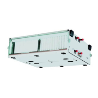
The product is composed of two parts: (a) probe and (b) upper shell. It shall be installed at position with
smooth air circulation. Position with 2-3 meters distance from fan or cooling coil is recommended to
achieve accurate measurement.
1. Punching hole on duct with diameter of 16mm (5/8”), use two tapping screws to fix the shell tightly on
duct with a diagonal distance of 92mm (3.6”).
2. Open the shell
3. Connecting signals in line with electrical diagrams.
4. Insert the probe in, use two tapping screws to fix the shell tightly on duct
5. Install the shell
6. Fix the screws
7. Screw driver #2, suggest using AMC-2 for cable protection
Wiring diagram
1: G power supply, 0VAC, +24VDC
2: G0 power supply, 24VAC, -24VDC
3: U1 JP1 = 1-2, humidity output voltage 0…10V or 210V (JP3)
3: I1 JP1 = 2-3, humidity output voltage 0…20mA or 4 20mA (JP3)
4: B1 Resistance temperature signal
5: M1 Resistance temperature signal
Output signal setting
By use of short cuts, output signal can change
in the range of 0…10V, 0…20mA or 2…10V,
4…20mA.
0-10 V is defined as factory settings, and
please change to 4…20mA before usage.
Below picture shows the position of short
cuts.
(.55 x 3 / 6.2)
91 (3.6)
68
Ц
2.7
Ч
47 (1.9)

 Loading...