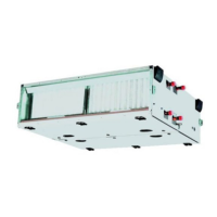
Do you have a question about the Carrier 39CQ Series and is the answer not in the manual?
Explains the integrative control solution with VFD and HMI for AHU control.
Describes three operating modes: Remote, Local (Automatic, Manual).
Details the SE6166 controller, its features, and technical specifications.
Describes the IM041 input and conversion control module and its specs.
Details features and technical specifications of the duct sensor.
Features and technical specifications of the indoor sensor.
Features and technical specifications for CO2 measurement.
Technical specifications of the actuator.
Describes the 8-inch touchscreen interface and its user-friendly design.
Monitor unit parameters and turn the unit on/off.
Interface to view fault information, time of occurrence, and fault type.
Access submenus like Unit Information, User Settings, System Settings.
Details on operating functions like on/off, fan speed, modes, and temperature settings.
Configure control strategies, fan speed, damper, valve, and humidifier settings.
Detailed wiring schematic for the AHU control system.
Detailed wiring schematic for the AHU control system components.
| Model | 39CQ Series |
|---|---|
| Type | Air Handler |
| Refrigerant | R-410A |
| Airflow | Up to 2000 CFM |
| Dimensions | Varies by model |
| Weight | Varies by model |
| Stages | Variable Speed |
| Voltage | 208/230V |
| Cabinet | Galvanized steel |
| Cooling Capacity | Up to 60, 000 BTU/h (5 tons) |


