11
Fig. 12 – Size 18
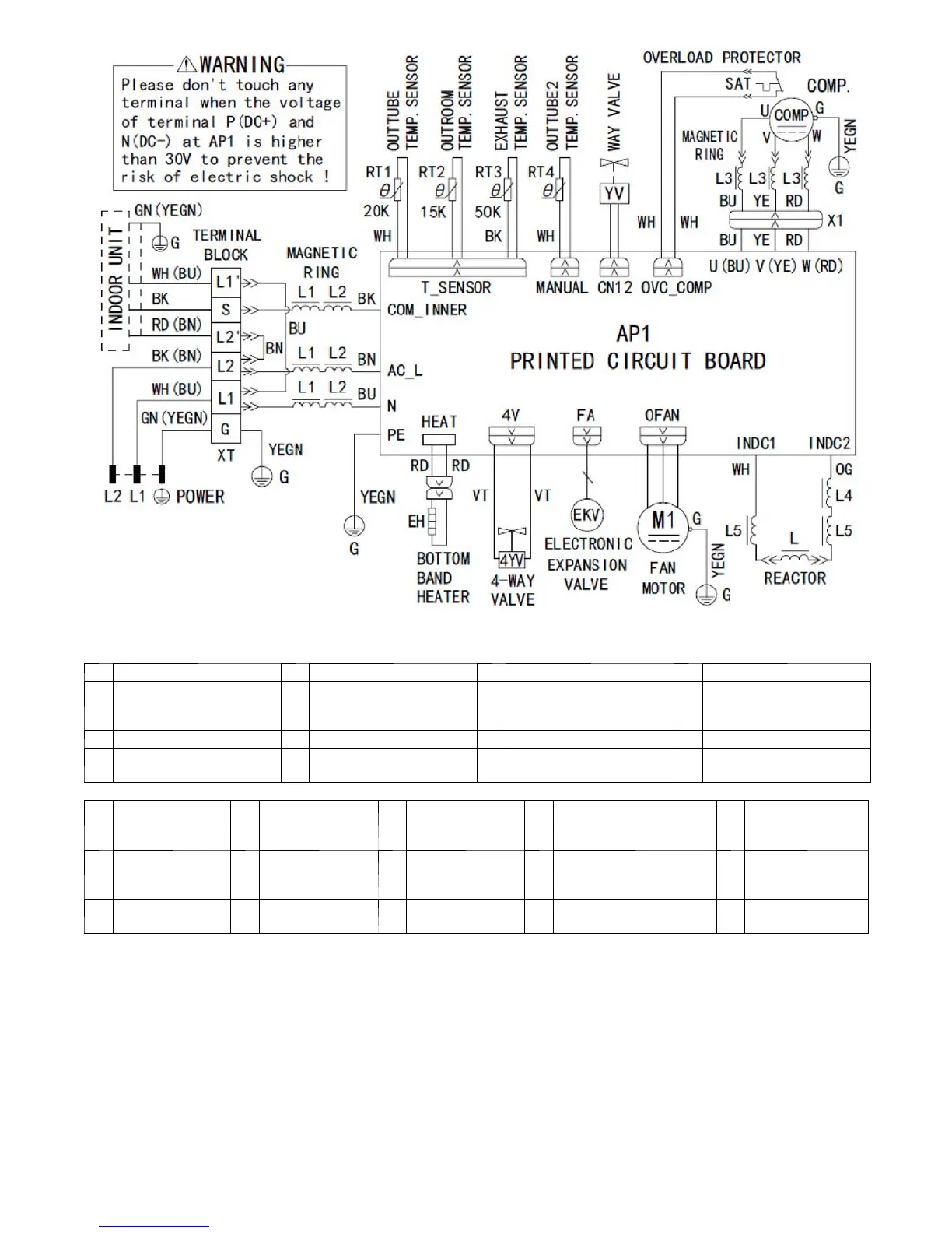
NOTE: These wiring diagrams are subject to change without notice. Refer to the one supplies with the unit.
1
Interface of neutral wire 5 Interface of DC motor 9 Interface of WIFI 13 Display interface
2 Interface of live wire 6 Up and Down s wing 3 10
Interface of left
and right swing
14
Interface of
communication wire for
neutral wire and live wire
3 Interface of fuse 7 Tube temperature sensor 11 Up and down s wing 2 / /
4 Interface of jumper cap 8
Ambient temperature
sensor
12 Up and down s wing 1 / /
1
Input of live wire
of power
4
Input of ground
wire of power
7
Neutral wire of
electric heater of
compression
10 Interface of fan 13
U.V.W. Three
phases of
compressor
2
Input of neutral
wire of power
5
Live wire of
electric heater
8
Neutral wire of
electric heater of
chassis
11
Interface 1 of electric
reactor
14 Input of overload
3
Communication
interface
6
Neutral wire of
4-wire valve
9
Live wire of
4-way valve
12
Interface 2 of electric
reactor
15 Temp. sensor
 Loading...