7
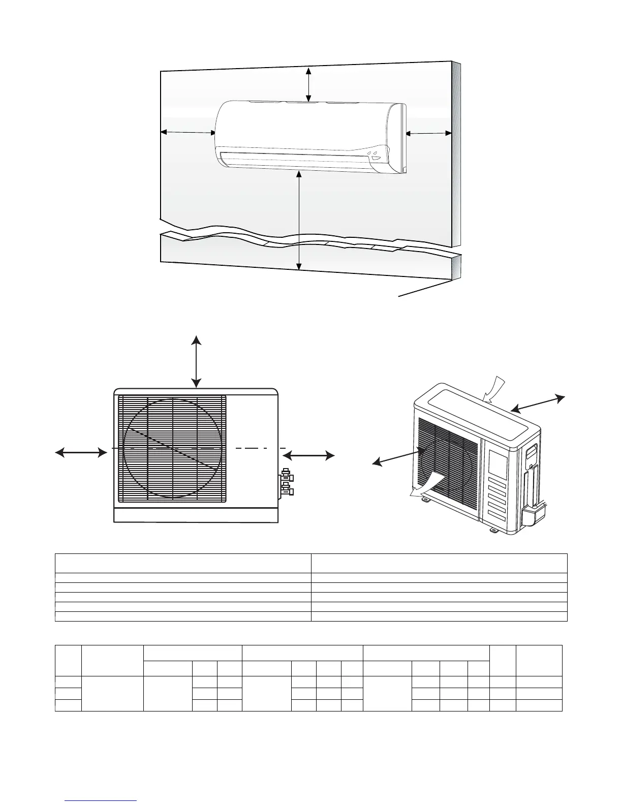
CLEARANCES - INDOOR
6
"
(0.15m
)
min.
5
"
(0.13m)
min.
6'
5
"
(0.13m)
min.
(1.8m)
CEILING
FLOOR
Fig. 7 – Indoor Unit Clearance
CLEARANCES - OUTDOOR
A
D
B
Air-outlet
Air-inlet
C
E
Fig. 8 – Outdoor Unit Clearance
UNIT
Minimum Value
in. (mm)
A 24 (609)
B 24 (609)
C 24 (609)
D 4 (101)
E 4 (101)
ELECTRICAL DATA
UNIT
SIZE
OPERVOLTAGE-
MAX / MIN*
COMPRESSOR OUTDOOR FAN INDOOR FAN
MCA
MAX FUSE
CB AMP
V/PH/HZ RLA LRA V/PH/HZ FLA HP W V/PH/HZ FLA HP W
9K
253 / 187 208-230/1/60
8.5 35
208-230/1/60
0.37 0.04 30
208-230/1/60
0.1 0.027 20 12 15
12K 9.5 40 0.37 0.04 30 0.1 0.027 20 13 20
18K 14.5 30 0.48 0.12 90 0.1 0.027 20 19 30
*Permissible limits of the voltage range at which the unit will operate satisfactorily
LEGEND
FLA -FullLoadAmps
LRA - Locked Rotor Amps
MCA - Minimum Circuit Amps
RLA - Rated Load Amps
 Loading...