14
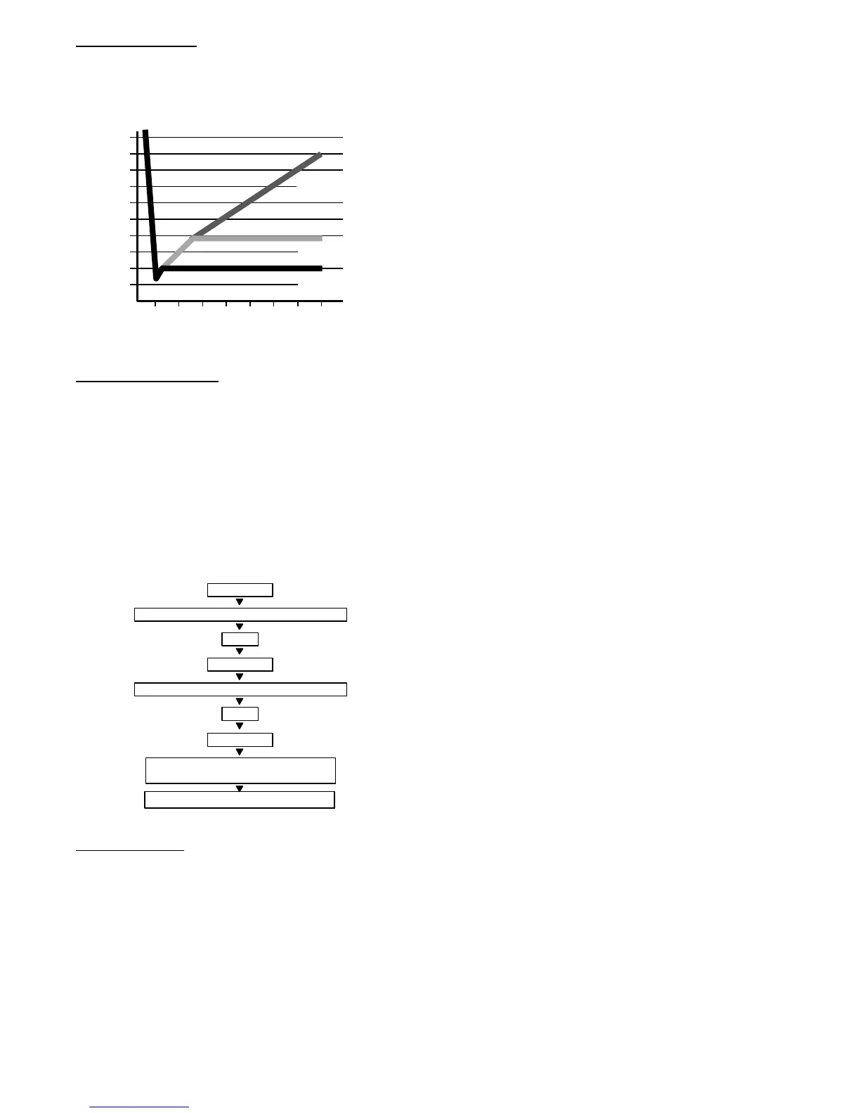
Deep Vacuum
Method
The deep vacuum method requires a vacuum pump capable of
pulling a vacuum of 500 microns and a vacuum gage capable of
accurately measuring this vacuum depth. The deep vacuum method
is the most positive way of assuring a system is free of air and
liquid water (see Fig. 16).
500
MINUTES
01234567
1000
1500
LEAK IN
SYSTEM
VACUUM TIGHT
TOO WET
TIGHT
DRY SYSTEM
2000
MICRONS
2500
3000
3500
4000
4500
5000
Fig. 16 – Deep Vacuum Graph
Triple Evacuation
Method
The triple evacuation process should be used in accordance with
the following figure. Refer to Fig. 17 and proceed as follows:
1 Pump system down to 500 microns and allow pump to con-
tinue operating for an additional 15 minutes.
2 Close service valves and shut off vacuum pump.
3 Connect a nitrogen cylinder and regulator to system and
open until system pressure is 2 psig.
4 Close service valve and allow system to stand for 1 hr .
During this time, dry nitrogen will be able to diffuse
throughout the system absorbing moisture.
5 Repeat this procedure as indicated in Fig. 17. The system is
freed of any contaminants and water vapor .
CHECK FOR TIGHT, DRY SYSTEM
(IF IT HOLDS DEEP VACUUM)
EVACUATE
BREAK VACUUM WITH DRY NITROGEN
WAIT
EVACUATE
RELEASE CHARGE INTO SYSTEM
BREAK VACUUM WITH DRY NITROGEN
EVACUATE
WAIT
Fig. 17 – Triple Evacuation Method
Final Tubing
Check
IMPORTANT: Check to be certain factory tubing on both
indoor and outdoor unit has not shifted during shipment.
Ensure tubes are not rubbing against each other or any sheet
metal. Pay close attention to feeder tubes, making sure wire ties
on feeder tubes ar e secure and tight.
CONTROL SYSTEM
The 40GRQ/ 38GRQ unit is equipped with a microprocessor
control to perform two functions:
1 Provide safety for the system
2 Control the system and provide optimum levels of comfort
and efficiency.
The main microprocessor is located on the control board of
outdoor unit. Outdoor and indoor units have thermistors used to
monitor the system operation to maintain the unit within acceptable
parameters and control the operating mode.
SYSTEM SAFETIES
3MinuteTimeDelay
In order to protect the compressor, there is a 3 minute delay on
break even if the control is calling for heating or cooling. The
compressor will have an additional 1 minute delay when powering
the unit on for the first time, or after a power failure.
Compressor Top Temperature Protection
The unit will stop working when the compressor top temperature
protector cuts off, and will restart after the compressor top
temperature protector restarts.
Compressor Discharge Temperature Protection
When the compressor discharge temperature reaches a higher one
than in normal operation, the running frequency will be limited
based on the algorithm presented below:
- When discharge B
208_F, prohibit increasing frequency
- When discharge B
217_F, prohibit decreasing frequency
- When discharge B
230_F, compressor stop operation
- When discharge B≤194_F, protection is released.
— If the compressor discharge temperature is lower than
194_F(90_C), there is no limit in the frequency.
— If this value is between 194_F and 221_F
(90<T5<105_C), the compressor will continue running
at the current frequency.
— If this value is now between 221_F and 239_F
(105<T5<115_C), the frequency will decrease to a lower
level every 3 minutes.
— When the compressor discharge temperature reaches a
value higher than 239_F(115_C), and has been running
at this condition for 5 seconds, the compressor stops.
Fan Speed Protection
When indoor fan speed is below 300RPM for a specific amount of
time the unit stops and the LED displays the failure.
Inverter Module Protection
The Inverter module is protected for abnormalities in current,
voltage and temperature. If abnormal values of any of these take
place, the corresponding code will be displayed in the indoor unit
and the unit will stop.
Indoor Fan Delayed Operation
Whe n the unit st arts up, the louve r will be active imme diately and the
indoor fa n will operate 10s later. If the operating mode is heati ng, the
indoor fa n will also be controll ed by the anti-col d blow functi on.
 Loading...