27
Outdoor Unit
09K/12K
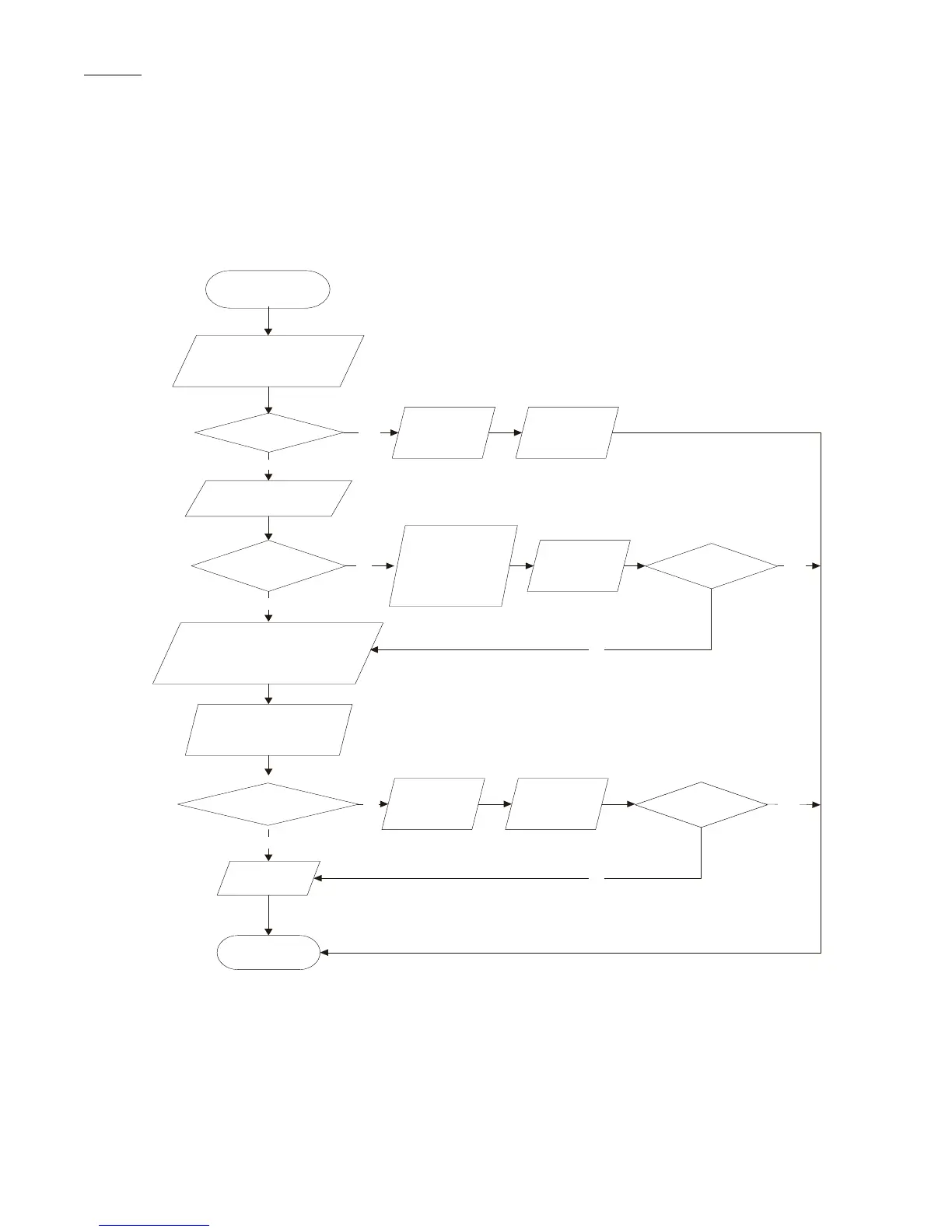
1. Capacity charging malfunction (outdoor unit malfunction) (AP1 below means control board of the outdoor unit)
Main detection points:
S Detect of the voltage of L1 and L2 terminals of XT wiring board is between 210VAC - 240VAC by alternating voltage meter.
S Is reactor (L) well connected? Is connection wire loosened or pulled out?
Yes
No
Turn on the unit
Use AC voltmeter to measure
the voltage on the two ends
of electrolytic capacitor
(see fig 30)
Voltage higher
than 200V?
Malfunction of
the outdoor
mainboard AP1
Replace outdoor
mainboard
Measure the voltage
input with AC voltmeter
(see fig 30)
Voltage within
180VAC~260VAC?
Shut down the power and wait 20
minutes; or use DC voltmeter to
measure the voltage on the two
ends of electrolytic capacitor
until the voltage is lower than 20V
Check the connection
of reactor and connection
wire
Is the wiring of
reactor L is normal?
Replace outdoor
mainboard AP1
End
Power supply is
abnormal; repair
the power supply
to restore the range
between 180VAC
~260VAC
Power on and
restart the unit
Is the malfunction
eliminated?
Is the malfunction
eliminated?
Connect the
connection
wire of reactor
L correctly
Power on and
restart the unit
Yes
Yes
Yes
Yes
No
No
No
No
Fig. 30 – Troubleshooting
 Loading...