Parts List
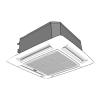
Indoor Unit
The following items are included with the indoor unit:
Table 1 - Installation Materials
Description Qty Usage
Baffle (size 18) 1 Required for fresh air intake
Mark hangers, piping and wiring Ioca-
Template 1 tions
NOTE: The grille and the User Interface are not included with
unit. For User Interface, a wireless remote, wired remote, or a
Zone Manager can be ordered.
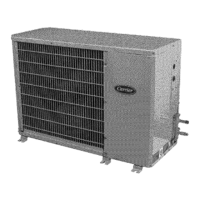
Outdoor Unit
The following items are included with the outdoor unit:
BODY
METERED FLOW
C00L[NG
38HDF018-036
Fig. 4 - 38HDF018-036
A09499
BODY
A09500
Fig. 5 - 38QRF018-036
Piston Flare
Model Filter Drier Pistons*
Cap Connector
38HDF _* _* _* _*
38QRF _* _* (qty 2) _* _* (qty 3)
Multiple pistons. Quantity varies with size.
These instructions cover the installation and start-up of the systems
listed in Table 2.
Table 2 - Matched Systems
INDOOR UNIT
SYSTEM SYSTEM
OUTDOOR UNIT MODEL NUM-
TYPE SIZE BER
018 38HDF018-3 40KMC018-3
Cooling 024 38HDF024-3 40KMC024-3
Only 030 38HDF030-3 40KMC03036-3
036 38HDF036-3/5/6 40KMC03036-3
018 38QRF018-3 40KMQ01824-3
024 38QRF024-3 40KMQ01824-3
Heat Pump 030 38QRF030-3 40KMQ03036-3
036 38QRF035-3/5/6 40KMQ03036-3
Cooling 018 38HDF018-3 40KMQ01824-3
with 024 38HDF024-3 40KMQ01824-3
Electric 030 38HDF030-3 40KMQ03036-3
Heat 036 38HDF036-3/5/6 40KMQ03036-3
SYSTEM REQUIREMENTS
Clearances
Allow sufficient space around the indoor and outdoor unit for
proper airflow circulation and servicing. Refer to Fig. 1 and Fig. 3
for minimum required clearances,
Piping: Piping and insulation is field supplied,
PiDinu Lenuths
The minimum length between the indoor and outdoor units is 10 fl
(3 m). Refer to table 3 for the maximum lengths allowed.
Table 3 - Maximum Refrigerant Line Lengths
Unit Max Line Max Elevation Max Elevation
Size Length* ft(m) (ID over OD) ft(m) (OD over ID) ft (m)
18K 200 (61) 65 (19.8) 200 (61)
24K 200 (61) 65 (19.8) 200 (61)
30K 200 (61) 65 (19.8) 200 (61)
36K 200 (61) 65 (19.8) 200 (61)
Note:For lengths greater than 25 ft (7.6 m), refer to the Duct Free Long
Line Guide.
Pipe Sizes
Refer to table 4 for pipe sizes.
Table 4 - Pipe Sizes
Pipe Sizes (in)
Unit Size Mix Phase - in Vapor - in
18K 3/8 5/8
24K 3/8 5/8
30K 3/8 3/4
36K 3/8 3/4
Note:Both lines need to be insulated using at least 1/2 inch closed foam
insulation.
Condensate Drain Pipe Sizes
Refer to table 5 for the required sizes.
Table 5 - Drain Pipe Sizes
Unit Size Inside Diameter - in
18K 1
24K 1
30K 1
36K 1
 Loading...