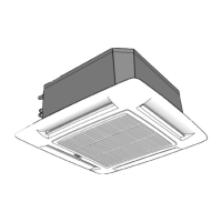
If you have two units installed in the same space and they need to
work independently, the remote controls and the units need to be
configured as follows:
Unit Configuration
Turn the unit off by pressing the IQL). Press and hold the/_ and
A
=_/_/IIbuttons of the remote control for more than 5 seconds. The
display will be cleared and the time segments will display the first
configuration item (rAdr=remote address) and the temperature
segments will display the default value of this configuration item
(ab=control of both indoor units). Press A and V to change the
default value to the new value of (a) or (b). Press the ;'/_ button to
,,..a.,,
transmit the new configuration to the unit. Press the 1_ button to
leave the configuration menu.
Remote Control Configuration
Turn the unit off by pressing the IQL)button. Press and hold the
A
v
and buttons for more than 5 seconds. The display will be
cleared and the time segments will display the first configuration
item (CH=remote address) and the temperature segments will
display the default value of this configuration item (Ab=control of
both indoor units).
Press A and V to change the default value to the new value of (a)
or (b). Press the ;'/_ button to transmit the new configuration to the
unit. Press the 1_ button to leave the configuration menu.
NOTE: When 30 seconds have elapsed and no buttons have been
pressed, the remote control will automatically exit the
configuration menu and resume its normal operation.
A wall mounted control or zone manager can be used to control a
unit or multiple units.
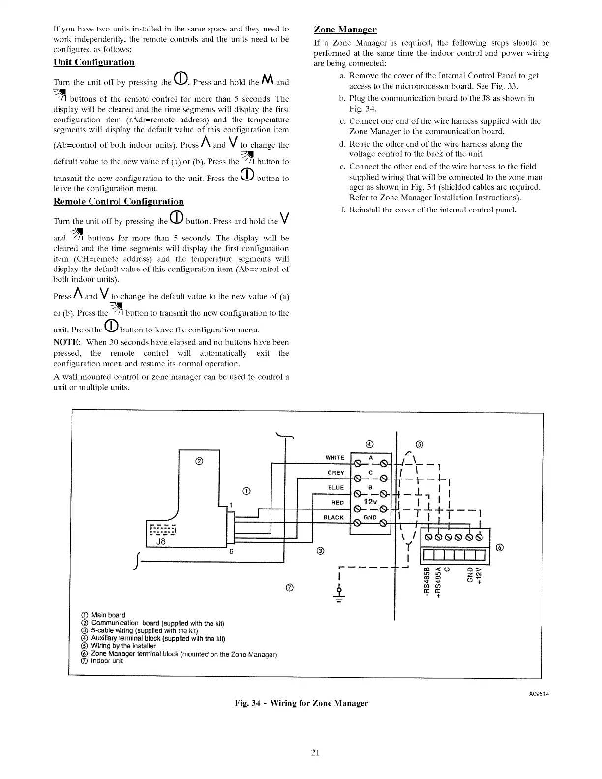
Zone Manager
If a Zone Manager is required, the following steps should be
performed at the same time the indoor control and power wiring
are being connected:
a. Remove the cover of the Internal Control Panel to get
access to the microprocessor board. See Fig. 33.
b. Plug the communication board to the J8 as shown in
Fig. 34.
c. Connect one end of the wire harness supplied with the
Zone Manager to the communication board.
d. Route the other end of the wire harness along the
voltage control to the back of the unit.
e. Connect the other end of the wire harness to the field
supplied wiring that will be connected to the zone man-
ager as shown in Fig. 34 (shielded cables are required.
Refer to Zone Manager Installation Instructions).
f. Reinstall the cover of the internal control panel.
/
J8
@
®
6
®
WHITE
GREY
®
r
I
® ±
(_) Main board
0 Communication board (suppl}ed with the kit)
0 5-cable wiring (supplied with the kit)
@ Auxiliary terminal block (supplied with the kit)
0 Wiring by the installer
(_) Zone Manager terminal block (mounted on the Zone Manager)
O Indoor unit
®
,.-.\
-F-. _
-- t---- ,1-i
;I
"' ]
! ,,
ii i i i L,,II®
Zcx_
t.0 t.O
Fig. 34 - Wiring for Zone Manager
A09514
21
 Loading...