INSTALLATION
Complete Pre-installation Checks
1. Unpack Unit - Store the indoor and outdoor units in the
original packaging until it is moved to the final site for in-
stallation. When unpacking indoor unit, be careful not to
lift unit by condensate drain discharge pipe or by refrigerant
connections.
2. Inspect Shipment - Upon receipt of shipment, check the
indoor and outdoor units for damage. If there is any dam-
age, forward claim papers directly to the transportation
company. Manufacturer is not responsible for damage in-
curred in transit.
3. Inspect Parts Supplied With Units - Check all items
against parts list (see page 4). If any items are missing, noti-
fy your distributor or Carrier office.
To prevent loss or damage, leave all parts in original packages until
installation.
Consider System Requirements
1. Consult local building codes and NEC for special installa-
tion requirements.
2. When deciding the location of the indoor and outdoor units,
ensure that the piping run does not exceed the allowed dis-
tances listed in Table 3.
3. Make sure the indoor and outdoor units are easily accessible
to electrical power.
4. Allow sufficient clearances for airflow, wiring, refrigerant
piping, and servicing the unit. See Fig. 2 and Fig. 3.
5. Condensate piping can be directed through the inside wall
to an approved drain or straight outside.
INSTALL INDOOR UNIT
Plan the installation carefully before you begin.
1. Select indoor unit location.
a. A location that can bear the weight of the unit.
b. Install the unit a centrally as possible in the room.
c. Choose a location that does not obstruct air circulation.
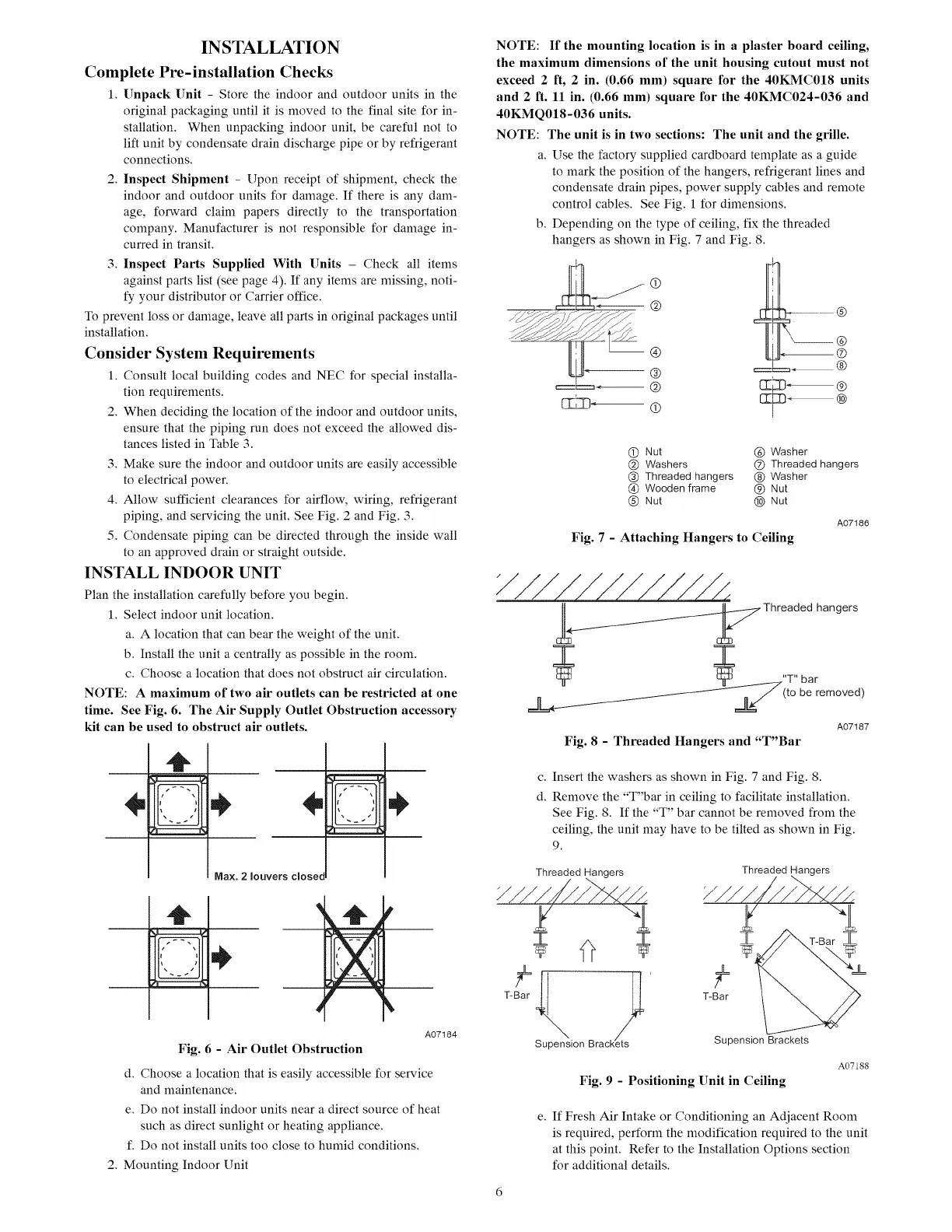
NOTE: A maximum of two air outlets can be restricted at one
time. See Fig. 6. The Air Supply Outlet Obstruction accessory
kit can be used to obstruct air outlets.
c-7=-=-c3
{, )
Max. 2 louvers closet
m
¢-7='=-.--I
r------
T--7=--=-C3
_t --" 1
_m,=_=_=_=___
A07184
Fig. 6 - Air Outlet Obstruction
d. Choose a location that is easily accessible for service
and maintenance.
e. Do not install indoor units near a direct source of heat
such as direct sunlight or heating appliance.
f. Do not install units too close to humid conditions.
2. Mounting Indoor Unit
NOTE: If the mounting location is in a plaster board ceiling,
the maximum dimensions of the unit housing cutout must not
exceed 2 It, 2 in. (0.66 mm) square for the 40KMC018 units
and 2 ft. 11 in. (0.66 mm) square for the 40KMC024-036 and
40KMQ018-036 units.
NOTE: The unit is in two sections: The unit and the grille.
a. Use the factory supplied cardboard template as a guide
to mark the position of the hangers, refrigerant lines and
condensate drain pipes, power supply cables and remote
control cables. See Fig. 1 for dimensions.
b. Depending on the type of ceiling, fix the threaded
hangers as shown in Fig. 7 and Fig. 8.
--®
®
(T) Nut ® Washer
@ Washers (_) Threaded hangers
® Threaded hangers @ Washer
® Wooden frame @ Nut
@ Nut @ Nut
A07186
Fig. 7 - Attaching Hangers to Ceiling
_4._.___._/_ Threaded hangers
3: 7=
"T" ar
(to be removed)
A07187
Fig. 8 - Threaded Hangers and "T"Bar
c. Insert the washers as shown in Fig. 7 and Fig. 8.
d. Remove the "T"bar in ceiling to facilitate installation.
See Fig. 8. If the "T" bar cannot be removed from the
ceiling, the unit may have to be tilted as shown in Fig.
9.
'l
T T
T-Bar T-Bar
• B kupenslon race s SupensionBrackets
Fig. 9 - Positioning Unit in Ceiling
A07188
e. If Fresh Air Intake or Conditioning an Adjacent Room
is required, perform the modification required to the unit
at this point. Refer to the Installation Options section
for additional details.
 Loading...