51
All the communication of 485 cables between each module and terminal module to the central controller are
double core shielded twisted-pair cables. Specic wiring dimensions are mentioned in the table below:
The length of signal line Wiring dimension
≤100 0.3 mm
2
×2
100<x≤200 0.5mm
2
×2
200<x≤300 0.75mm
2
×2
300<x≤400 1.25mm
2
×2
400<x≤500 2mm
2
×2
Installation conditions
• Do not install near devices that produce electrical interference such as AC motors, radio transmitters
like network routers and consumer electronics.
• Other electrical noise producers could include computers, auto-door openers, elevators, or other
equipment which can produce noise.
• Do not install in wet locations.
• It will cause failure if you install it in a place that shakes violently.
• Do not install in a place where it is exposed to direct sunlight or near to the heat. This will cause
failure.
A
B
C
D
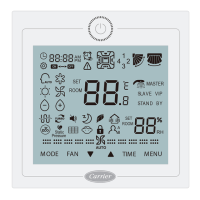
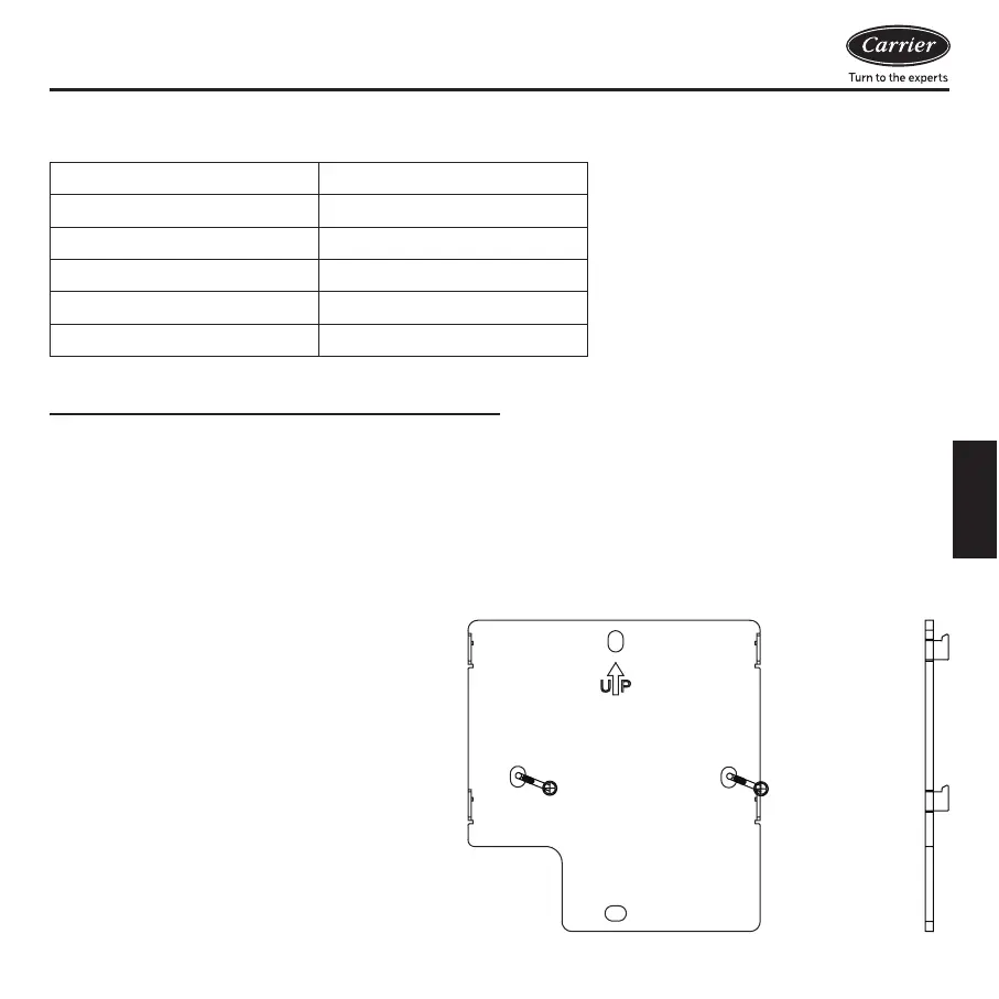
Mounting Control
First, attach the mounting plate to the wall.
Using a job box is preferred. Use A and B
holes for a 86mm box, use C and D holes for
a 120mm box. Please take note of the UP
indicator.
Wiring diagram and Installation
English