6
INSTALLATION
Step 1 — Unpack and Inspect Units —
Units are
packaged for shipment to avoid damage during normal transit
and handling. It is the receiving party’s responsibility to inspect
the equipment upon arrival. Any obvious damage to the carton
and/or its contents should be reported on the bill of lading and a
claim should be filed with the transportation company and the
factory. The unit should always be stored in a dry place and in
the proper orientation as marked on the carton.
After determining the condition of the carton exterior, carefully
remove each unit from carton and inspect for hidden damage.
Check to make sure that items such as thermostats and
controllers are accounted for whether packaged separately or
shipped at a later date. Any hidden damage should be recorded,
a claim should be filed with the transportation company, and
the factory should be notified. If a claim for shipping damage is
filed, the unit, shipping carton, and all packing must be retained
for physical inspection by the transportation company. All units
should be stored in the factory shipping carton with internal
packaging in place until installation.
PROTECTING UNITS FROM DAMAGE — Do not apply
force or pressure to the coil, piping, or drain stub-outs during
handling. All units should be handled by the chassis or as close
as possible to the unit mounting point locations.
Unit must always be properly supported. Temporary supports
used during installation or service must be adequate to hold
unit securely. To maintain warranty, protect units against
hostile environments (such as rain, snow, or extreme
temperature), theft, vandalism, and debris on jobsite.
Equipment covered in this manual is not suitable for outdoor
installations. Do not allow foreign material to fall into drain
pan. Prevent dust/debris from being deposited on motor, fan
wheels, and coils. Failure to do so may have serious adverse
effects on unit operation, and in case of motor and blower
assembly, this may result in immediate or premature failure.
Failure of any unit caused by deposits of foreign material on
motor or blower wheels will not be covered by manufacturer’s
warranty. Some units and/or job conditions may require some
form of temporary covering during construction.
PREPARING JOBSITE FOR UNIT INSTALLATION —
To save time and to reduce the possibility of costly errors, set
up a complete sample installation in a typical room at jobsite.
Check all critical dimensions such as pipe, wire, and duct
connections requirements. Refer to job drawings and product
dimension drawings as required. Instruct all trades in their
parts of the installation. Units must be installed in compliance
with all applicable local code requirements.
IDENTIFYING AND PREPARING UNITS — Be sure
power requirements match available power source. Refer to
unit nameplate and wiring diagram. In addition:
• Check all tags on unit to determine if shipping screws are
to be removed. Remove screws as directed.
• Rotate fan wheel by hand to ensure that fan is
unrestricted and can rotate freely. Check for shipping
damage and fan obstructions. Adjust blower motor as
required.
Step 2 — Position the Unit
Install unit in a location that meets the following requirements:
• Allow adequate space for installation, service clearance,
piping and electrical connections, and necessary
ductwork. For specific unit dimensions, refer to Table 1
and Fig. 2. Allow clearance according to local and
national codes.
• Confirm that the ceiling is able to support the weight of
the unit. See Table 1 for nominal weight.
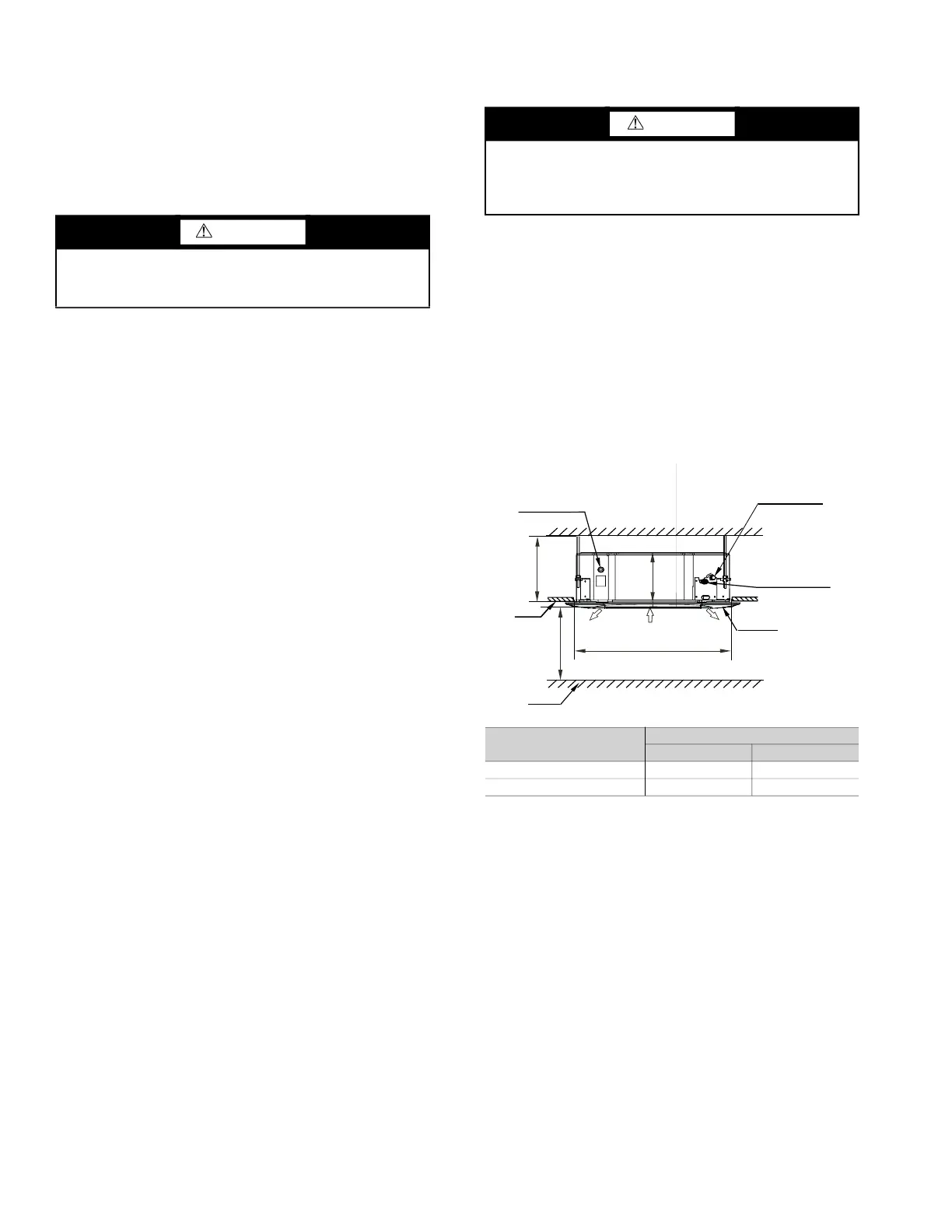
• There should be enough room within the false ceiling for
installation and maintenance. See Fig. 3 below.
• The false ceiling should be horizontal and leveled.
• Install the unit in a location within the room that allows
uniform air flow in all directions.
Fig. 3 —False Ceiling Installation
Select the unit position with the following points in mind:
• The unit should be installed in a position that is suitable
to support the total weight of the unit, refrigerant piping,
and condensate.
• Proper access should be provided for maintenance for
refrigerant piping, EEV (electronic expansion valve),
electrical box, and condensate pump. A 2-ft clearance is
recommended all around the unit.
• The unit should be at least 3-
1
/
4
feet from a wall or
similar obstruction. See Fig. 4 below.
CAUTION
To avoid equipment damage, do not lift unit by the drain
pipe or refrigerant piping. The unit should be lifted using
the mounting brackets.
DANGER
Units must not be installed where they may be exposed to
potentially explosive or flammable atmosphere. If this
instruction is not followed exactly, a fire or explosion may
result, causing property damage, injury, or loss of life.
40VMF UNIT SIZE
DIMENSION (in.)
A H
009-015 9 10-
1
/
4
018-048 11-
3
/
4
13
A
H
>8-1/4 ft.
Connect to the outlet
of
drainage pipe
Connection port of
(Gas side)
refrigerant pipe
(Liquid side)
Connection port
of refrigerant pipe
Floor
Ceiling
Panel
Air outlet Air inlet
2-7/8 ft. (Ceiling hole)
Air outlet