7
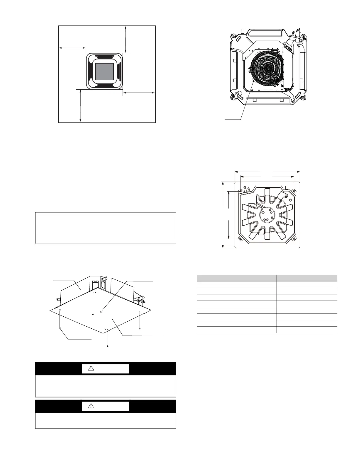
Fig. 4 —Distance from Wall or Obstruction
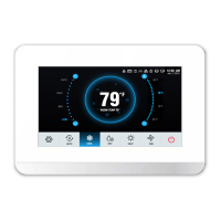
• Do not position the unit where the discharge air could
blow directly on the thermostat.
• Recommended distance between 2 units is 10 feet to
avoid conflicting airflow and recirculation.
• The unit should not be positioned directly above any
obstruction.
• The unit must be installed square and level.
• Condensate drain should have sufficient downward slope
(1 inch per 100 inches) in any horizontal run between
unit and drain. Maximum condensate lift is 29-
1
/
2
inches.
In case of new construction, once the unit is installed, cover the
fan motor opening using the construction cover board to avoid
any dust and debris from settling inside the unit. Use the M6
bolt, washer and nut as shown in Fig. 5 below.
Fig. 5 —Paper Board Mounting Hole Locations
See Fig. 6 for an example of some buffer locations.
Fig. 6 —Example of Buffer Locations
Step 3 — Mount the Unit
INSTALLING HANGER BOLTS — Install the hanger bolts
at the locations shown in Fig. 7. Use 3/8-inch all-threaded rod.
For unit weight, see Table 3.
Fig. 7 —Mounting Hole Locations
Table 3 — Unit Weight
*Includes grille weight.
MOUNTING UNIT — The unit can now be lifted on to the
hanging rods for mounting.
1. Use rods and fasteners to suspend the unit at the factory-
provided mounting holes.
2. Adjust the height of the unit until the bottom (without
grille) is level with the false ceiling.
3. Secure the unit in position with locknuts and washers on
both sides of the unit bracket. Ensure that the threaded
rod does not protrude more than 2 inches below the
mounting brackets as shown in Fig. 8.
IMPORTANT: Be sure that the ceiling grid is supported
separately from the unit. The ceiling grid must not be
supported by an part of the unit or any associated
wiring or piping work.
CAUTION
Remove all buffers between the fan and the flared mouth
before installing the indoor unit. Failure to do so will cause
damage to the fan motor.
CAUTION
To avoid equipment damage, ensure the unit is placed
horizontally.
40 in. MIN.
40 in. MIN.
40 in. MIN.
40 in. MIN.
a40-1720
Unit body
Install the paper board
Central hole
Screw M6×12
40VMF UNIT WEIGHT (lb)*
009A 71.0
012A 71.0
015A 71.0
018A 86.0
024A 86.0
030A 86.0
036A 86.0
048A 86.0