14
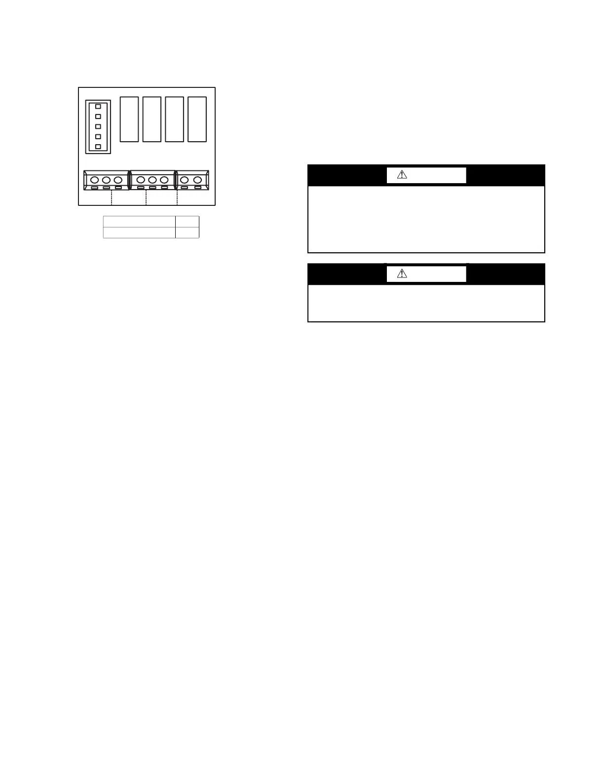
ACB Interface — The ACB interface is a dry contact
board that can output up to four signals controlling devices.
Refer to Fig. 23 for connecting devices to ACB interface board.
Fig. 23 —ACB Interface
START-UP
Pre-Start Check —
Once installation is complete, make
the following pre-start checks:
1. All indoor and outdoor units are properly installed.
2. All piping and insulation is complete.
3. All electrical connections (both power and control) are
properly terminated.
4. All condensate drains are installed correctly.
5. The power supply is of the right voltage and frequency.
6. The units are properly grounded in accordance with
current electrical codes.
7. Suction and liquid line isolation valves are in open
position.
System Operation Check — Once the installation
and pre-start checks are completed, follow these steps:
1. Using the remote controller, select cooling or heating
mode to check the operation of the system.
2. While the system is in operation, check the following on
indoor unit:
a. Switches or buttons on the remote controller are
easy to push.
b. Indicator light is showing normal operation and no
error is indicated.
c. Swing mode of air louvers is working (if
applicable to unit).
NOTE: When attaching a supply duct to the side of the cas-
sette to feed a small adjacent space, the corresponding louver
must be closed to deliver airflow to the supply duct.
d. Drain pump operation is normal (if applicable).
e. No abnormal vibration or noise is noticed.
3. While the system is in operation, check the following on
the outdoor unit:
a. No abnormal vibration or noise is noticed.
b. Condenser fan is in operation.
c. Indicator light is showing normal operation and no
error is indicated.
NOTE: If the unit is turned off or restarted, there is a time
delay of 3 minutes for compressor to start from time power is
restored.
MAINTENANCE
EVERY 3 MONTHS:
• Check air filter condition. Clean or replace if necessary.
EVERY 6 MONTHS:
Follow 3-month maintenance schedule. In addition:
• Clean condensate tray with suitable cleaning agent.
• Clean the grille and panel.
EVERY 12 MONTHS:
Follow 6-month maintenance schedule. In addition:
• Be sure all electrical connections are secure.
• Check condensate pump operation.
• Check the heating and cooling action to confirm proper
operation.
INDOOR UNIT ADDRESSING
For proper system operation, each indoor unit must have a
unique address set from 0 to 63. When setting an address by
remote controller, the outdoor units, indoor units, and MDC
must be powered on. If FE is displayed on the LED screen or
display board, this unit has no address. After setting all indoor
units’ addresses, turn off the power supply to all indoor units to
clear errors.
Indoor units’ addressing can be distributed automatically in the
heat pump system. When dip switch “S6” on the outdoor units’
main PCB board is set to 00 (default set in factory), indoor
units are set for auto-addressing. When powering on for the
first time, it takes 6 minutes or more to finish auto-addressing
each indoor unit. The heat recovery system cannot accomplish
this function at this time.
Wireless Remote Controller (40VM900001) —
Indoor unit addressing can be performed using the wireless
remote controller. When using the wireless controller, user
must maintain a line of sight with receiver on the indoor unit.
See Fig. 24 for a description of buttons on wireless remote.
LEGEND:
ACB
—
Auxiliary Control Board
AUXH
—
Output For Auxiliary Heat
CTON
—
Output For Cooling Operation
FAN
—
Output For Fan Operation
HTON
—
Output For Heating Operation
MAX AMPS 1A
MAX VOLTAGE 24V
CAUTION
When servicing or repairing this unit, use only factory-
approved service replacement parts. Refer to the rating
plate on the unit for complete unit model number, serial
number, and company address. Any substitution of parts or
controls not approved by the factory will be at the owner’s
risk and may result in equipment damage.
CAUTION
To avoid equipment damage, do not attempt to reuse any
mechanical or electrical controllers that have been wet.
Replace defective controller.