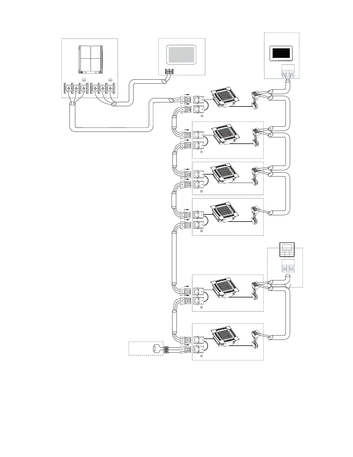
Fig. 22 —Typical Heat Pump Communication Wiring Diagram
P Q
X Y
X Y
Centralized controller
outdoor unit
P Q
P Q
P Q
P Q
P Q
P Q
L1
L3
L5
L6
L7
L8
L9
L10
L11
L3
L3
L3
L3
Indoor unit 1#
HA HB
Indoor unit 2#
HA HB
Indoor unit 3#
HA HB
Indoor unit 4#
HA HB
Indoor unit 5#
HA HB
Indoor unit 6#
HA HB
P
Q
Network Resistor
HA HB
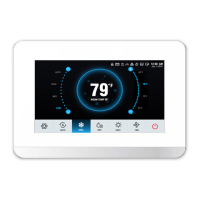
Touch screen
NOTE: 24 v. DC Power
wired controller
(Field Supplied)
wired controller
HA HB
NOTE: Power from IDU
MAXIMUM WIRING LENGTH
L1+L3 </= 3937 ft 18 AWG, 2-Core Stranded Shield
L5 </= 3937 ft 18 AWG, 2-Core Stranded Shield
L6+L7+L8+L9 </= 820 ft 18 AWG, 2-Core Stranded Shield
L10+L11 </= 820 ft 18 AWG, 2-Core Stranded Shield
LEGEND
IDU— Indoor Unit
NOTE: Network resistor is shipped with the outdoor unit for field installation on
heat pump systems.