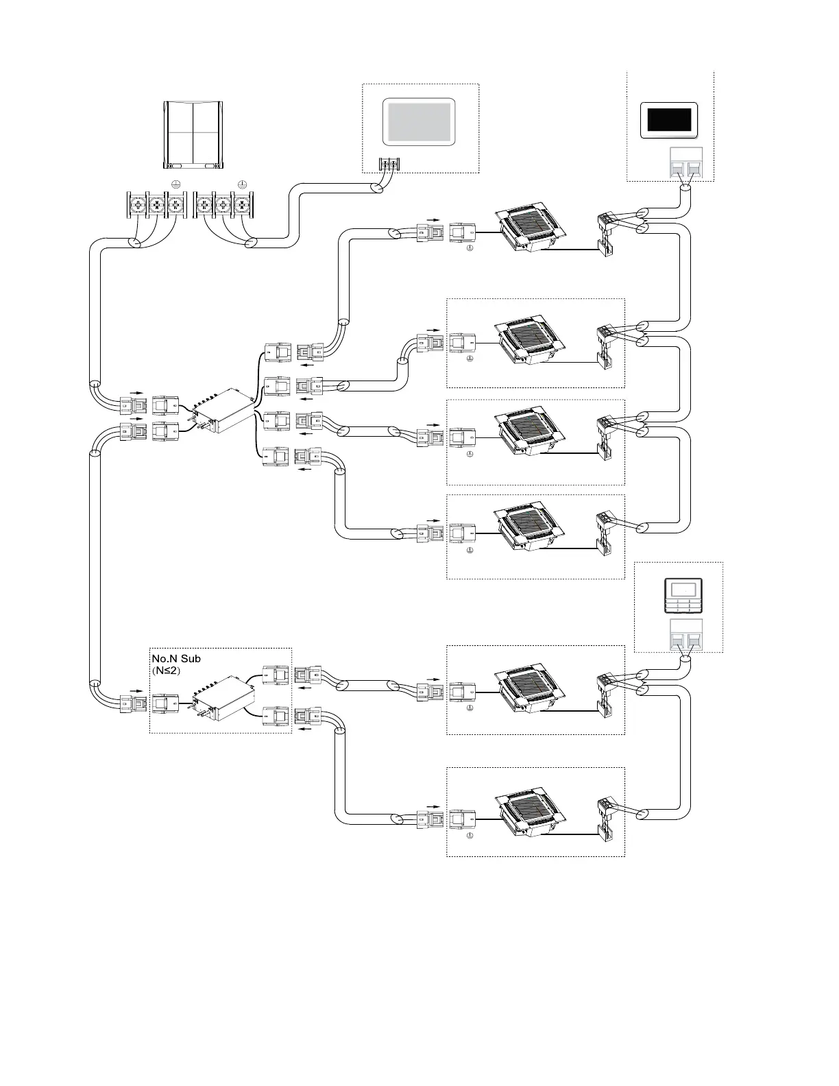
Fig. 21 —Typical Heat Recovery Communication Wiring Diagram
P Q
X Y
X Y
MDC unit
Centralized controller
outdoor unit
P Q
P Q
P Q
P Q
P Q
P Q
To No.1
indoor
To No.2
indoor
To No.3
indoor
To No.4
indoor
To No.1
indoor
To No.2
indoor
To Sub MDC
To outdoor
Main MDC unit
To outdoor
L1
L2
L3
L3
L3
L3
L4
L4
L5
L6
L7
L8
L9
L10
L11
Indoor unit 1#
HA HB
Indoor unit 2#
HA HB
Indoor unit 3#
HA HB
Indoor unit 4#
HA HB
Indoor unit 5#
HA HB
Indoor unit 6#
HA HB
HA HB
Touch screen
NOTE: 24 v. DC Power
wired controller
(Field Supplied)
wired controller
HA HB
NOTE: Power from IDU
MAXIMUM WIRING LENGTH:
L1+L2 </= 3937 ft 18 AWG, 2-Core Stranded Shield
L3 </= 3937 ft 18 AWG, 2-Core Stranded Shield
L4 </= 3937 ft 18 AWG, 2-Core Stranded Shield
L5 </= 3937 ft 18 AWG, 2-Core Stranded Shield
L6+L7+L8+L9 </= 820 ft 18 AWG, 2-Core Stranded Shield
L10+L11 </= 820 ft 18 AWG, 2-Core Stranded Shield
LEGEND
MDC —
Multiport Distribution Controller
IDU
—
Indoor Unit