19-EN 20-EN
– 10 –
EN
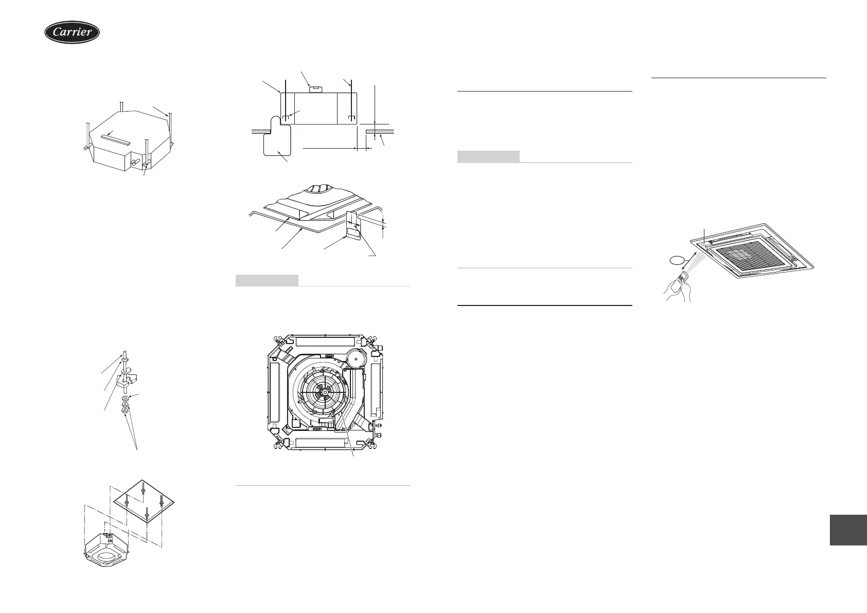
◆ Installation of ceiling opening
and hanging bolt
Hanging bolt
Level vial
Hanging bracket
y Attach a nut (M10 or W3/8: not supplied) and the
Ø34 washer (supplied) to each hanging bolt.
y Insert a washer on both sides of the T groove of the
hanging bracket of the indoor unit, and hang the
indoor unit.
y Check that the four sides of the indoor unit are level
using a level vial (levelness: 5 mm or less).
y Detach the installation gauge (accessory) from the
installation pattern.
y Using the installation gauge, check and adjust the
positional relation between the indoor unit and the
ceiling opening (1) (10 to 35 mm: 4 sides) and the
hanging-up height (2) (12
+5
0
mm: 4 corners).
(How to use the installation gauge is printed on the
gauge.)
Hanging bolt
(M10 or W3/8)
* Procure hanging bolts
and nuts locally.
Washer (Accessory)
To prevent the bolt from
falling off (for safety),
be sure to set it just
under the hanging
bracket as shown in the
gure.
Nut (M10 or W3/8)
Eccentric washer
(Accessory)
* Install with the marking
“UP” facing up.
Nut (M10 or W3/8)
Level vial (levelness: 5 mm or less)
Hanging bolt
(1) 10 to 35 mm
Installation gauge
Ceiling
board
(2) 12
+5
0
mm
Indoor unit
Hanging
bracket
Indoor unit
Ceiling board
Installation
gauge
(1) 10 to
35 mm
(2)
12
+5
0
mm
REQUIREMENT
Before installation of the indoor unit, be sure to
remove the tape for transportation between the
fan and the bell mouth. Running the unit without
removing the tape may damage the fan motor.
Be sure to remove the tape for
transportation between the fan
and the bell mouth.
Installation of ceiling panel
(Sold separately)
Install the ceiling panel according to
Installation Manual attached with it after piping /
wiring work has completed.
Check that installation of indoor unit and ceiling
opening part is correct, and then install it.
REQUIREMENT
y Joint the connecting sections of ceiling panel,
ceiling surface, ceiling panel and indoor unit closely.
Any gap between them will cause air leakage and
the generate condensation or water leakage.
y Remove the adjust corner caps at the four corners
of the ceiling panel, and then install the ceiling panel
onto the indoor unit.
y Make sure that the claws of the four adjust corner
caps are securely t.
* Improper tting of the claws may cause water
leakage.
Installation of remote
controller (Sold separately)
For installation of the wired remote controller, follow
the Installation Manual attached with the remote
controller.
y Pull out the remote controller cord together with the
refrigerant pipe or drain pipe.
Be sure to pass the remote controller cord through
upper side of the refrigerant pipe and drain pipe.
y Do not leave the remote controller at a place exposed
to the direct sunlight and near a stove.
Wireless type
The sensor of indoor unit with wireless remote
controller can receive a signal by distance within
approx. 8 m. Based upon it, determine a place where
the remote controller is operated and the installation
place.
y Operate the remote controller, conrm that the
indoor unit receives a signal surely, and then install it.
y Keep 1 m or more from the devices such as
television, stereo, etc.
(Disturbance of image or noise may generate.)
y To prevent a malfunction, select a place where is not
inuenced by a uorescent light or direct sunlight.
y Two or more (Up to 6 units) indoor units with wireless
type remote controller can be installed in the same
room.
Signal receiving unit
8 m
IM_1115350185.indb 10IM_1115350185.indb 10 26/6/2566 BE 14:5726/6/2566 BE 14:57
 Loading...