15-EN 16-EN
– 8 –
EN
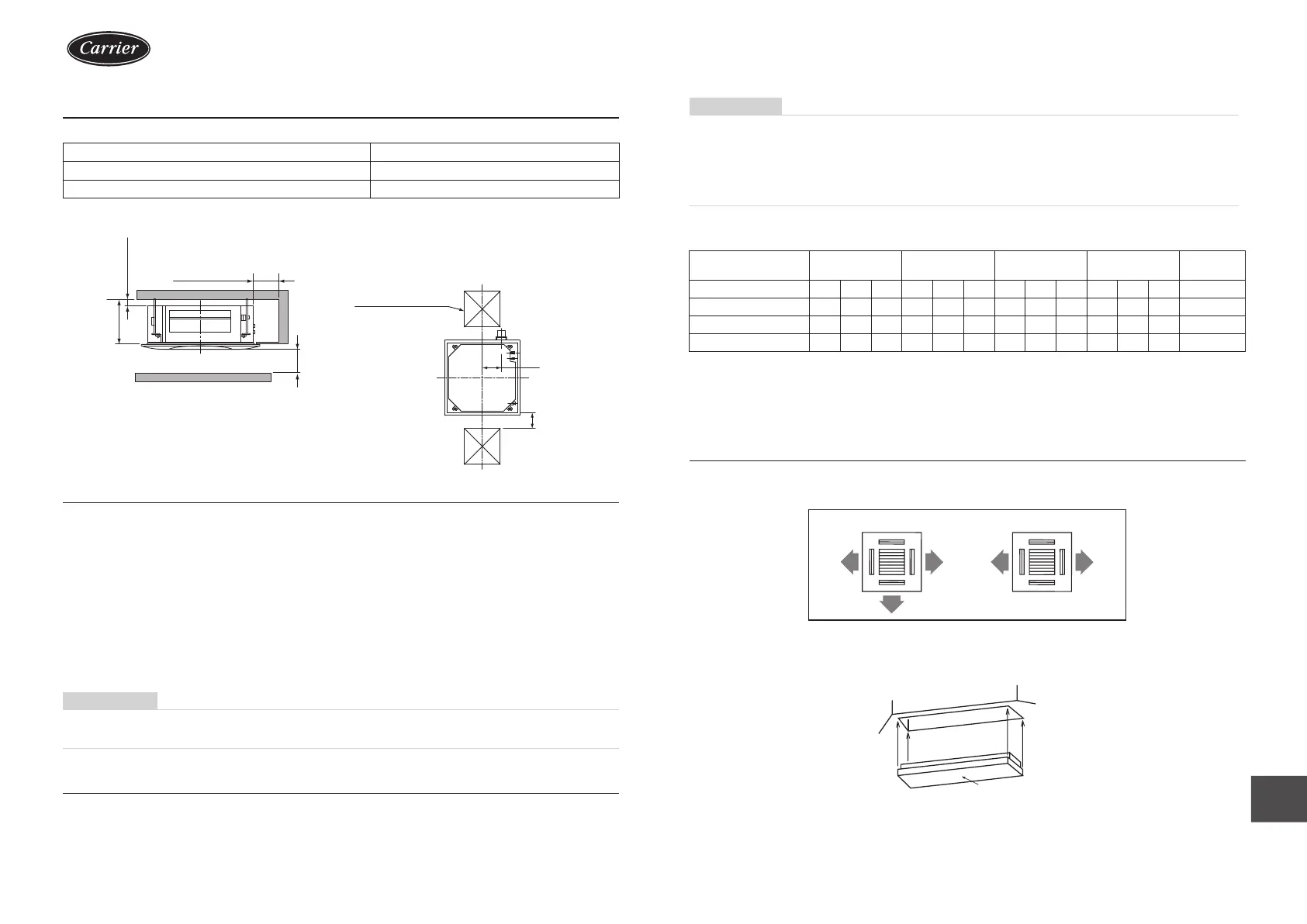
Installation space
Secure the specied space in the gure for installation and servicing.
Model A mm
009S ~ 030S 271 or more
036S ~ 056S 334 or more
1000 or more
When incorporating
esh-air intake box
q When incorporating fresh air intake box
(sold separately)
Provide an inspection opening at the outside-air
intake box side.
Check port
(450 × 450 mm)
Check port
(450 × 450 mm)
238 mm
200 mm
1000
or more
unit: mm
Obstacle
15 or more
Selection of installation place
In case of continued operation of the indoor unit under high-humidity conditions as described below, dew may
condense and water may drop.
Especially, high-humidity atmosphere (dew point temperature : 23 °C or more) may generate dew inside the ceiling.
1. Unit is installed inside the ceiling with slated roof.
2. Unit is installed at a location using inside of the ceiling as fresh air take-in path.
3. Kitchen
◆ Advice
y Set a service check opening panel at right side of the unit (size: 450 × 450 mm or more) for piping, maintenance,
and servicing.
y If installing a unit at such place, put insulating material (glass wool, etc.) additionally on all the positions of the
indoor unit which come to contact with high-humidity atmosphere.
REQUIREMENT
When the humidity inside the ceiling seems to be higher than 80%, attach a heat insulator to the side (top)
surface of the indoor unit. (Use a heat insulator that is 10 mm or more thick.)
Ceiling height
When the height of the ceiling exceeds the distance of the item Standard / 4-way in Table on the next page, the hot
air is difcult to reach the oor.
Therefore, it is necessary to change the setup value of the high ceiling switch or discharge direction.
The high-ceiling setting is also necessary when installing separately sold lters.
REQUIREMENT
y When using the air conditioner with 2-way / 3-way discharge system, a strong wind blows directly if the ceiling
height is lower than the standard.
Therefore, change the setting switch according to height of the ceiling.
y When using the high ceiling (1) or (3) with 4-way discharge system, the draft is apt to be felt due to drop of the
discharge temperature.
y 009S Type and 012S Type air conditioners cannot be installed on a high ceiling.
q Height list of ceiling possible to be installed
(Unit: m)
Model 009S ~ 012S 015S ~ 018S 024S ~ 030S 036S ~ 056S
Setup of high
ceiling
Discharge direction
4-way 3-way 2-way 4-way 3-way 2-way 4-way 3-way 2-way 4-way 3-way 2-way SET DATA
Standard (Factory default) 2.7 2.8 3.0 2.8 3.2 3.5 3.0 3.3 3.6 3.9 4.2 4.5 0000
High ceiling (1) — — — 3.2 3.5 3.8 3.3 3.5 3.8 4.2 4.4 4.6 0001
High ceiling (3) — — — 3.5 3.8 — 3.6 3.8 — 4.5 4.6 — 0003
The lighting time of the lter sign (notication of lter cleaning) on the remote controller can be changed according
to installation conditions.
When it is difcult to obtain satisfactory heating due to location place of the indoor unit or the structure of the room,
the detection temperature of heating can be raised.
Discharge direction
As shown in the gure below, air discharge directions can be selected according to the shape of the room and the
location of the indoor unit installation.
3 directions 2 directions
Use a shielding plate kit (sold separately) to change discharge directions.
Discharge directions are limited. Follow the Installation Manual supplied with the shielding plate kit.
Shielding plate
(Sold separately)
IM_1115350185.indb 8IM_1115350185.indb 8 26/6/2566 BE 14:5726/6/2566 BE 14:57
 Loading...